
Camera rotating device

A technology of rotating device and camera, which is applied in the direction of image communication, TV, color TV parts, etc. It can solve the problems of camera rotation and adjustment installation angle, difficulty in adjusting camera angle, and reduced service life, so as to achieve low manufacturing cost and improve use. Life, good effect

Inactive Publication Date: 2019-07-30
北京宇视科技有限公司
View PDF8 Cites 5 Cited by
  • Summary
  • Abstract
  • Description
  • Claims
  • Application Information

AI Technical Summary

Problems solved by technology

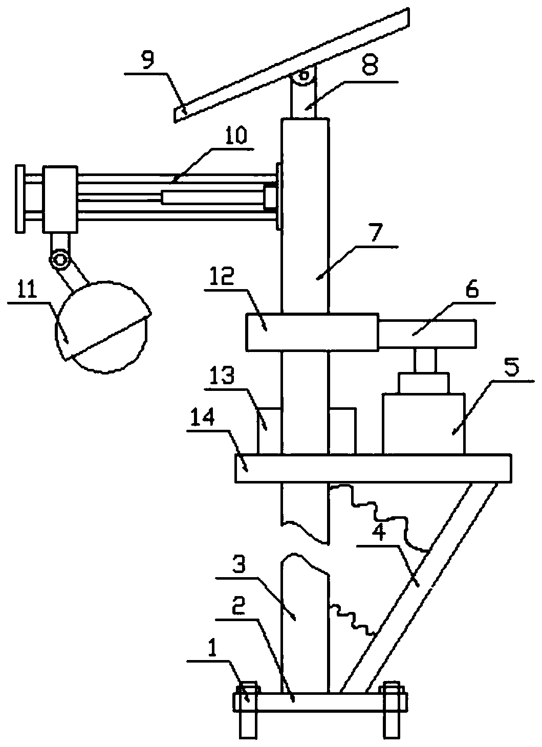
However, after the camera installed at a high place is installed, it is difficult to adjust the angle of the camera, and many installation brackets are fixed in structure. Facing different monitoring environment areas, when the camera installed outdoors needs to adjust the monitoring angle, the operation is inconvenient, and the camera cannot be used flexibly. Rotate the environment to adjust the installation angle, the installation of the camera is subject to certain limitations, and the camera installed outdoors is susceptible to damage from rain and snow after long-term use, resulting in a decrease in its service life. To sum up, outdoor installation The current camera can no longer meet the needs of people, in order to solve the above problems, therefore, a camera rotation device is designed

Method used


Image

  • Camera rotating device
  • Camera rotating device
  • Camera rotating device

Examples


Embodiment Construction

[0026] The following will clearly and completely describe the technical solutions in the embodiments of the present invention with reference to the accompanying drawings in the embodiments of the present invention. Obviously, the described embodiments are only some, not all, embodiments of the present invention. Based on the embodiments of the present invention, all other embodiments obtained by persons of ordinary skill in the art without making creative efforts belong to the protection scope of the present invention.

[0027] In the description of the present invention, it should be noted that the orientation or positional relationship indicated by the terms "vertical", "upper", "lower", "horizontal" etc. is based on the orientation or positional relationship shown in the drawings, and is only In order to facilitate the description of the present invention and simplify the description, it does not indicate or imply that the device or element referred to must have a specific o...


PUM


Abstract

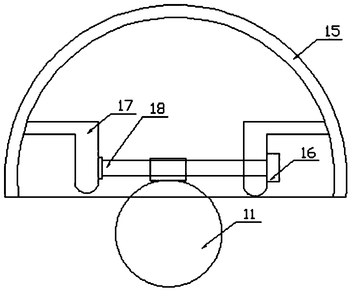
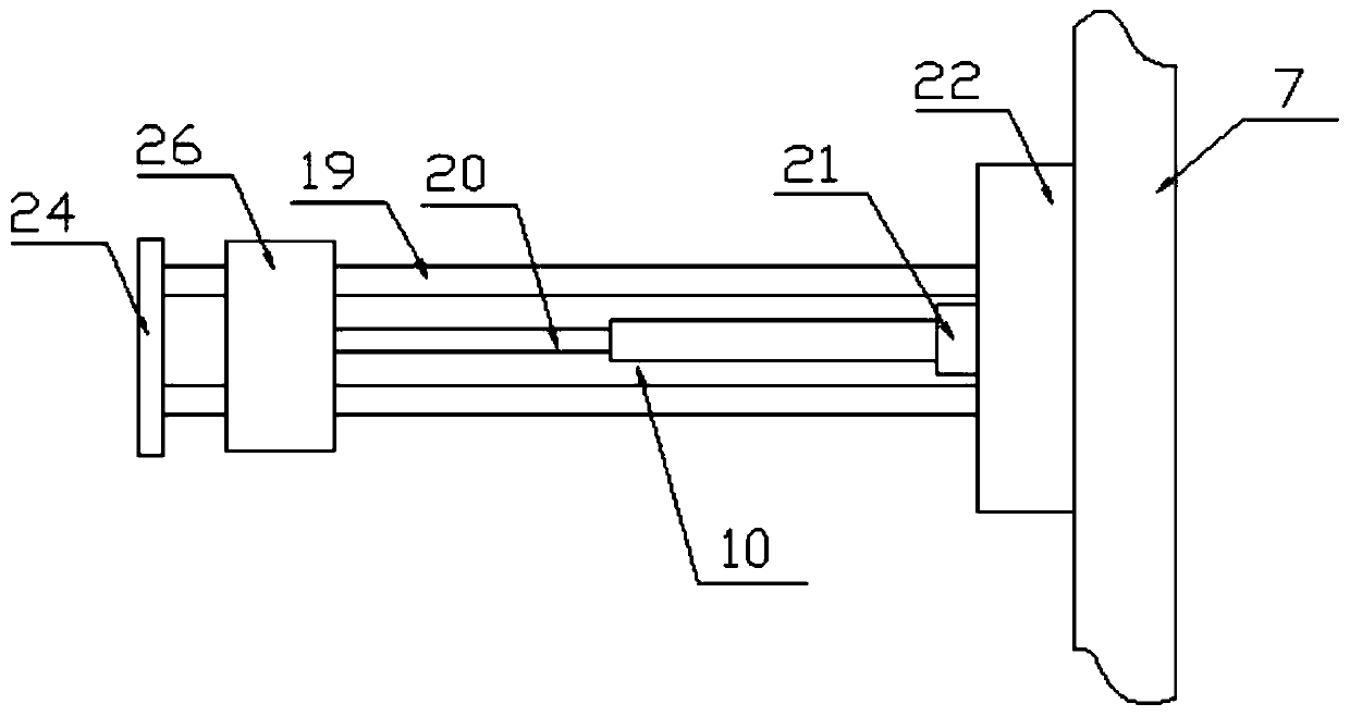
The invention discloses a camera rotating device. The camera rotating device comprises a base, an installation supporting plate, a rotating rod, a moving assembly and a camera, wherein a support is fixedly arranged at the center of the top of the base; the top of the support is fixedly connected with the bottom side surface of the installation supporting plate; a driving motor is arranged on one side of the top of the installation supporting plate; an output shaft of the driving motor is connected with a first gear; a bearing seat is arranged on the top, positioned at one side of the driving motor, of the installation supporting plate; the bearing seat is in interference connection with the rotating rod; a second gear sleeves the middle of the rotating rod; the second gear and the first gear are engaged each other; and the moving assembly is transversely arranged on one side of the rotating rod. The device has the beneficial effects that a protective cover is installed on the camera inthe prior art, a connecting frame, a rotating shaft and a micro-motor structure are arranged in the protective cover, and the rotating shaft can be rotated to store the camera into the protective cover when the camera is not used outdoors, so that damage to the camera is reduced, and the service life of the camera is prolonged.

Description

technical field [0001] The invention relates to the technical field of camera rotation installation, in particular to a camera rotation device. Background technique [0002] Camera, also known as computer camera, computer eye, electronic eye, etc., is a video input device, which is widely used in video conferencing, telemedicine and real-time monitoring. Ordinary people can also talk and communicate with each other through the network with images and sounds through the camera. In addition, people can also use it for various popular digital images and audio-visual processing. With the continuous improvement of people's and social security awareness, cameras are widely used in all walks of life. In daily life, our common cameras are installed on municipal traffic roads, residential communities, garden landscapes, etc. Usually, most of these cameras are installed at high places through mounting brackets, which is convenient for monitoring a wide range and avoids damage. Howe...

Claims


Application Information

Patent Timeline
Patent Type & Authority Applications(China)
IPC IPC(8): F16M11/42F16M11/10F16M11/18F16M11/08F16M11/04H04N5/225
CPCF16M11/42F16M11/10F16M11/18F16M11/08F16M11/04H04N23/00
Inventor 吴晶明
Owner 北京宇视科技有限公司
Learn More