Supercharge Your Innovation With Domain-Expert AI Agents!

Method for electrohydraulic forming and associated device

A technology of electro-hydraulic forming and equipment, which is applied in the field of electro-hydraulic forming, and can solve the problems of increasing the molding time and long time of parts

Inactive Publication Date: 2019-08-02
ADM28 S AR L
View PDF7 Cites 0 Cited by
  • Summary
  • Abstract
  • Description
  • Claims
  • Application Information

AI Technical Summary

Problems solved by technology

The time required to fill the cavity with pressurized water can be relatively long, especially when using a pump with a limited flow rate
Also, between each cycle of molding a new part, the cavity must be filled with liquid and pressurized by a pump, which increases part molding time

Method used


Image

  • Method for electrohydraulic forming and associated device
  • Method for electrohydraulic forming and associated device
  • Method for electrohydraulic forming and associated device

Examples


Embodiment Construction

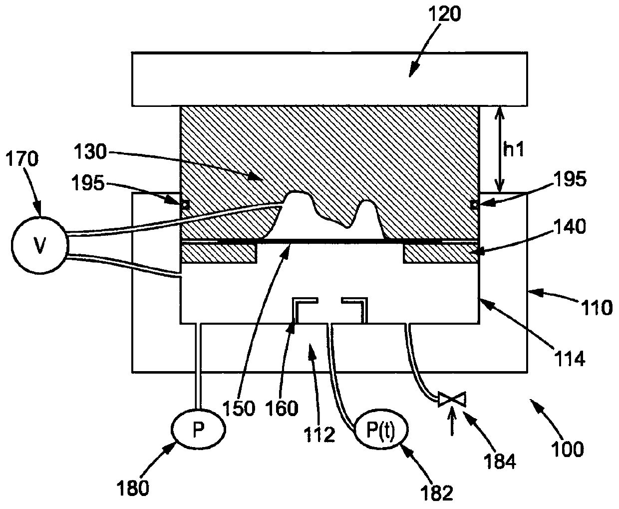
[0059] figure 1 An electrohydraulic forming apparatus 100 according to a first embodiment is shown. The electrohydraulic forming apparatus 100 comprises a frame 110 and a movable plate 120 mounted with a mold 130 platen. The plate 120 , and the model 130 are movable relative to the frame 110 .

[0060] The blank 150 to be deformed is placed between the mold 130 and the holder 140 . A stock holder is used to hold the blank based on the model 130 . In particular, the holder faces the mold, in particular the wall of the mold, and engages with the mold to support the blank. In the above embodiments, the holder 140 is fixed to the model 130 . Therefore, the holder 140 is separated from the frame.

[0061] The frame 110 includes a bottom wall 112 and side walls 114 . Bottom wall 112, side walls 114 and blank 150 together define a cavity for filling with a liquid, such as water. Sealing means such as O-rings 195 on the side walls of the mold 130 are used to seal the cavity. ...


PUM


Abstract

The invention relates to a method for electrohydraulic forming a material blank (150), in which: a material blank (150) to be shaped is placed between a mould (130) and a blank holder (140); a tight cavity containing electrodes (160) is filled with liquid up to a predetermined liquid level; the material blank (150) is brought into contact with the liquid of the cavity; the material blank is hydraulically preformed; and the material blank is electrohydraulically formed. The liquid of the cavity is pressurised for the hydraulic preforming by moving all or part of one of the walls of the cavity.

Description

technical field [0001] The invention relates to a method and equipment suitable for electrohydraulic forming. Background technique [0002] By applying dynamic pressure, electrohydraulic forming can be used to deform the blank according to the model. To this end, an electrical discharge is generated between at least two electrodes in a cavity filled with a liquid, such as water. Thus, an electric arc is formed between the two electrodes, resulting in an elevated temperature gradient and vaporization of the liquid. The pressure wave, commonly referred to as a "shock wave," moves at high speed and presses the blank against the model. Compared to other forming methods, electrohydraulic forming is particularly advantageous for obtaining sculpted details and / or sharp edges and / or improved elongation at break on the part to be formed because it reduces springback. [0003] In some cases, especially when the part to be formed is particularly deep, multiple successive discharges ...

Claims


Application Information

Patent Timeline
Patent Type & Authority Applications(China)
IPC IPC(8): B21D26/021B21D26/12B21D26/023
CPCB21D26/021B21D26/023B21D26/12
Inventor 吉莱斯·阿弗里劳德罗曼·默西厄
Owner ADM28 S AR L
Features
  • R&D
  • Intellectual Property
  • Life Sciences
  • Materials
  • Tech Scout
  • Unparalleled Data Quality
  • Higher Quality Content
  • 60% Fewer Hallucinations
Learn More