Supercharge Your Innovation With Domain-Expert AI Agents!

Electrohydraulic forming device

a technology of electrohydraulic forming and electrodes, applied in the field of electrohydraulic forming devices, can solve the problems of electrode wear rapid, electrode wear, and increase the distance between electrodes,

Active Publication Date: 2022-05-24
ADM28 S AR L
View PDF5 Cites 0 Cited by
  • Summary
  • Abstract
  • Description
  • Claims
  • Application Information

AI Technical Summary

Benefits of technology

This configuration reduces maintenance costs and extends electrode lifespan, maintaining efficiency by distributing wear over a larger surface, allowing for longer device operation with consistent pressure generation and enabling easier assembly and operation.

Problems solved by technology

However, electrohydraulic forming has disadvantages.
One of the disadvantages of electrohydraulic forming is that the electrodes wear rapidly.
Therefore, the distance between the electrodes increases and the electrical discharge is weaker.
The efficiency of the electrohydraulic forming reduces.
The replacement of the electrodes incurs additional maintenance costs and involves a reduction of the rate of output following temporary immobilisation of the apparatus.
However, the replacement of an electrode involves the changing of the entire electrohydraulic forming chamber which incurs higher maintenance costs than for the other devices of the prior art and a longer temporary immobilisation of the apparatus for replacing the electrode.

Method used


Image

  • Electrohydraulic forming device
  • Electrohydraulic forming device
  • Electrohydraulic forming device

Examples


first embodiment

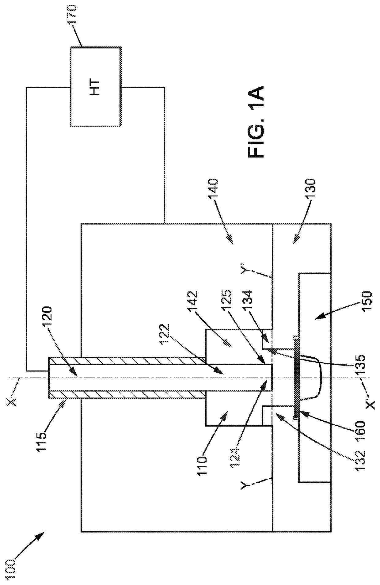
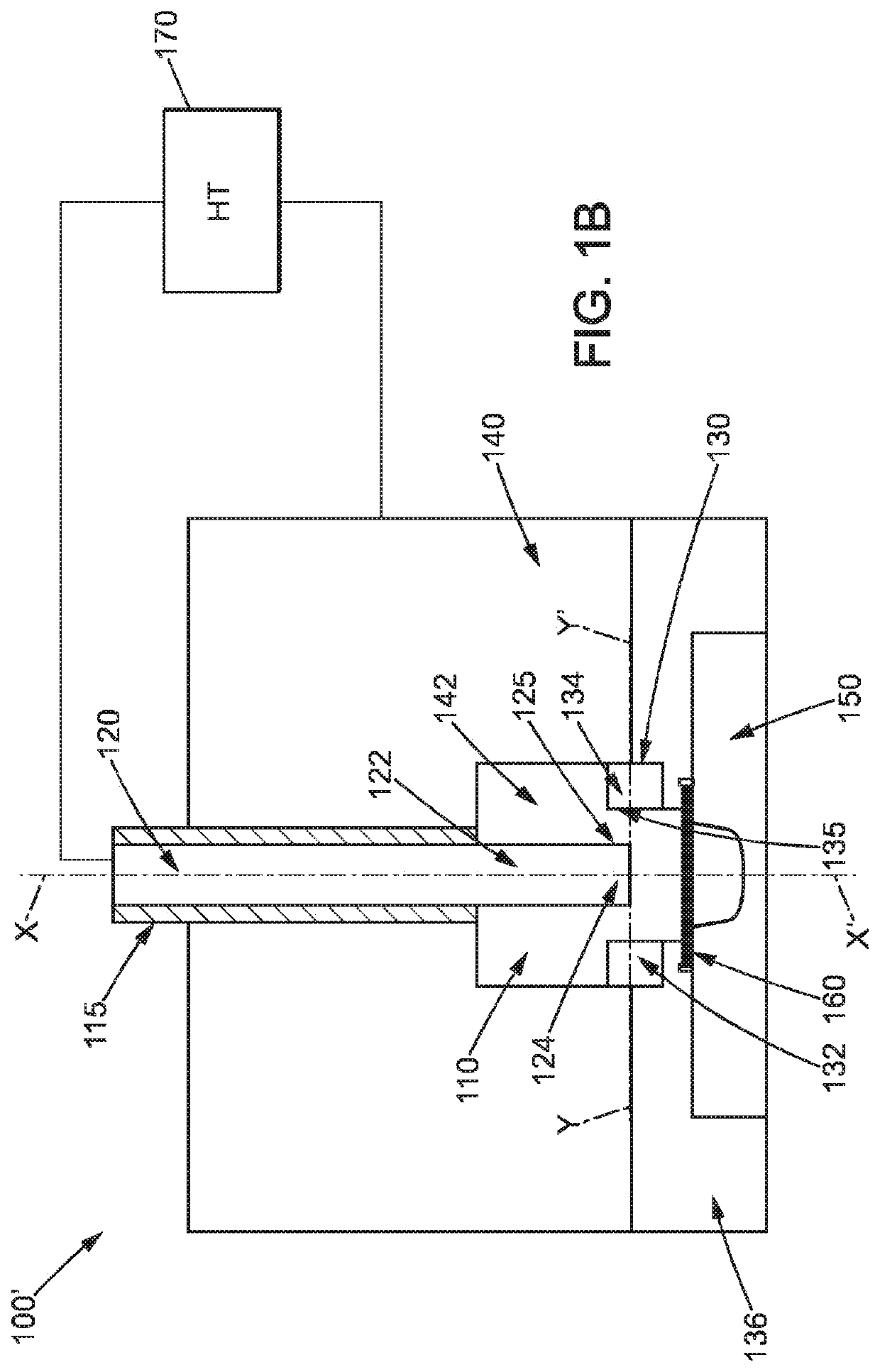
[0036]FIG. 1A shows an electrohydraulic forming device according to the invention. The electrohydraulic forming device 100 comprises an electrohydraulic forming chamber 110, a central electrode 120 and a peripheral electrode 130. The central electrode 120 extends in a longitudinal direction XX′ and comprises a first end 122 arranged inside the electrohydraulic forming chamber 110. The peripheral electrode 130 has an end 132 arranged at a distance from and around the end 122 of the central electrode 120. The end 132 of the peripheral electrode 130 extends in a transverse plane relative to said central electrode 120, that is to say in the plane perpendicular to the axis XX′.

[0037]The electrohydraulic forming device 100 also comprises a body 140 and a mould 150. The body 140 comprises an inner cavity 142 and is crossed by the central electrode 120. The inner cavity 142 of the body forms, with the end 132 of the peripheral electrode 130, the electrohydraulic forming chamber 110.

[0038]Th...

second embodiment

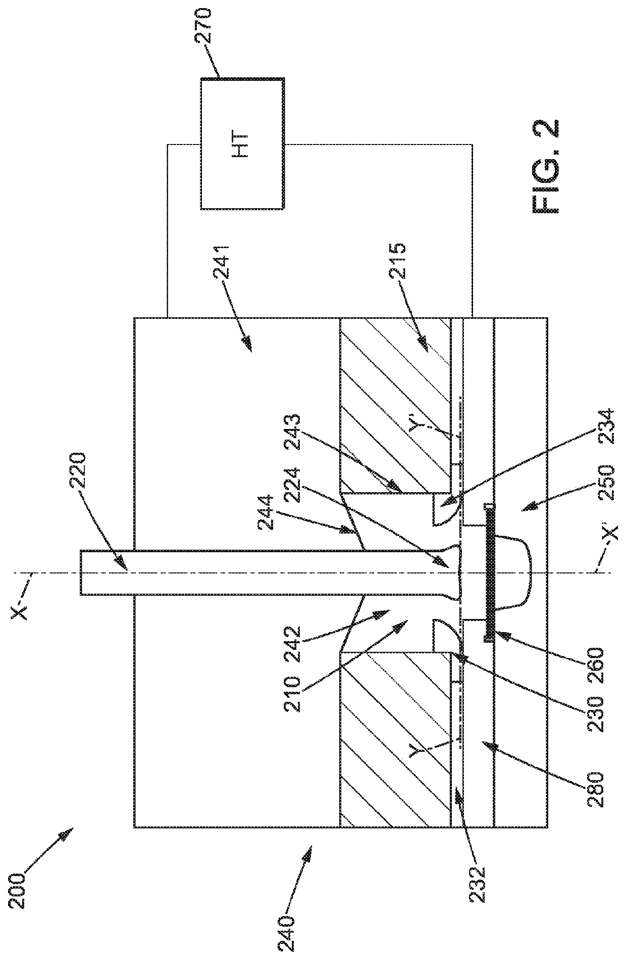
[0051]FIG. 2 shows an electrohydraulic forming device according to the invention. The electrohydraulic forming device 200 is similar to same shown with reference to FIG. 1A in that it also comprises an electrohydraulic forming chamber 210, a central electrode 220, a peripheral electrode 230, a body 240 and a mould 250. As opposed to the electrohydraulic forming device shown with reference to FIG. 1A, the electrohydraulic forming device 200 further comprises an additional part 280 serving as a blank holder. The device further comprises an electrode holder 232 on which is attached the peripheral electrode 230. The body 240 further comprises an electrical insulator 215 positioned, no longer between the body and the central electrode as illustrated with reference to FIGS. 1A and 1B, but for example, on the lower portion of the body 240. In the embodiment illustrated here, the electrical insulator 215 constitutes the lateral wall 243 of the cavity 240 partially forming the electrohydraul...


PUM

PropertyMeasurementUnit
distanceaaaaaaaaaa
electrical insulatoraaaaaaaaaa
electricalaaaaaaaaaa

Abstract

An electrohydraulic forming device for forming a blank of material includes: —an electrohydraulic forming chamber, —at least one central electrode extending in a so-called longitudinal direction and comprising a first end arranged inside the electrohydraulic forming chamber, —a body provided with a bore for introducing each central electrode into the electrohydraulic forming chamber, the electrohydraulic forming chamber being partially formed by said body, —a mould, and —at least one peripheral electrode electrically insulated from each central electrode, arranged at a distance from and around the end of a central electrode, and extending in a transverse plane relative to said central electrode.

Description

BACKGROUNDTechnical Field[0001]The present invention relates to an electrohydraulic forming device.Description of the Related Art[0002]Electrohydraulic forming makes it possible to deform a blank of material against a mould by applying a dynamic pressure. To this end, an electrical discharge is generated between at least two electrodes placed in a chamber filled with liquid, for example water. An electric arc is therefore formed between the two electrodes causing a high temperature gradient and the vaporisation of the liquid. A pressure wave, also commonly known as “shock wave”, moves at high speed and presses the blank of material against the mould. Electrohydraulic forming is particularly advantageous in comparison with the other forming methods since it makes it possible to have a reduced springback and to obtain improved engraving type details and / or square edges and / or local elongations before rupture on the parts to be formed.[0003]However, electrohydraulic forming has disadva...

Claims


Application Information

Patent Timeline
Patent Type & Authority Patents(United States)
IPC IPC(8): B21D26/12
CPCB21D26/12
Inventor AVRILLAUD, GILLESDEROY, JULIENPECQUOIS, ROMAINTHOUET, PIERRE
Owner ADM28 S AR L
Features
  • R&D
  • Intellectual Property
  • Life Sciences
  • Materials
  • Tech Scout
  • Unparalleled Data Quality
  • Higher Quality Content
  • 60% Fewer Hallucinations
Learn More