Supercharge Your Innovation With Domain-Expert AI Agents!

Chamber for electrohydraulic forming

a technology of electrohydraulic forming and chamber, applied in the field of electrohydraulic forming and electrohydraulic forming chamber, can solve problems such as the need for cycle time, and achieve the effect of reducing cycle time and effective

Active Publication Date: 2018-09-20
ADM28 S AR L
View PDF2 Cites 0 Cited by
  • Summary
  • Abstract
  • Description
  • Claims
  • Application Information

AI Technical Summary

Benefits of technology

The invention aims to provide a solution for forming materials while reducing the cycle time and ensuring a similar result. The use of a non-metallic coating helps prevent the formation of an electrical arc between the electrohydraulic discharge system and the internal wall, which could damage the system and increase cycle time. By reducing the dimensions of the discharge chamber and the volume of fluid needed to fill it, the risk of electrical arc is minimized, resulting in faster production rates and increased efficiency. Additionally, the coating is produced in an electrically insulating material to further mitigate the risk of electrical arc.

Problems solved by technology

However, one of the drawbacks lies in the cycle time necessary for the forming of a piece, as indicated in the U.S. Pat. No. 7,493,787.

Method used


Image

  • Chamber for electrohydraulic forming
  • Chamber for electrohydraulic forming
  • Chamber for electrohydraulic forming

Examples


Embodiment Construction

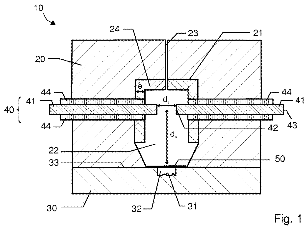
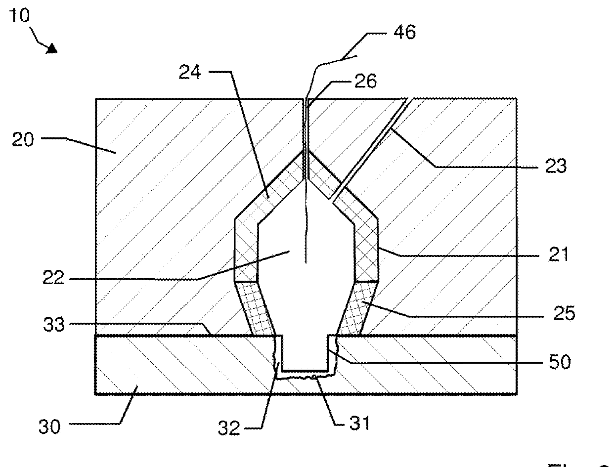
[0039]An electrohydraulic forming chamber 10 for forming a piece 50 according to an embodiment of the invention is illustrated in FIG. 1. The pieces to be formed can be of flat form, or, as a variant, of tubular form. The pieces can also be preformed by conventional stamping techniques.

[0040]This electrohydraulic forming chamber is used in the context of a conventional forming method which will be recalled later.

[0041]The electrohydraulic forming chamber 10 is produced in two parts. The electrohydraulic forming chamber 10 comprises a first part, called discharge frame 20, and a second part, called die 30. The discharge frame 20 can represent an upper part of the electrohydraulic forming chamber (according to the orientation of the figures) and the die 30 can represent a lower part, as illustrated in the figure. As a variant, and without departing from the scope of the invention, it is possible to envisage the discharge frame 20 representing a lower part of the electrohydraulic formi...


PUM

PropertyMeasurementUnit
dielectric strengthaaaaaaaaaa
thicknessaaaaaaaaaa
dielectric strengthaaaaaaaaaa

Abstract

An electrohydraulic forming chamber to form a workpiece. The chamber includes a discharge frame that has an inner wall which delimits a discharge space provided to hold a volume of fluid, a female mold having a forming space which includes an impression configured to be complementary to the shape of the workpiece after deformation, and an electrohydraulic discharge system. The workpiece is placed between the discharge space and the forming space before the electrohydraulic discharge system is activated. Upon activation of the electrohydraulic discharge system, the workpiece is catapulted against the impression in the forming space and is deformed accordingly. All or part of the inner wall is provided with a non-metal coating.

Description

FIELD OF THE INVENTION[0001]The present invention relates to the field of forming, and more particularly to the field of electrohydraulic forming. The present invention relates to an electrohydraulic forming chamber, notably for forming pieces of small dimensions.STATE OF THE ART[0002]Hydraulic forming methods are generally used as manufacturing methods, notably for pieces of complex forms. They involve using the pressure of a fluid, preferably a liquid, to produce the plastic deformation of a steel plate held in a mold. The fluid then acts on the steel plate to make it follow the form of the mold. This fluid can be pressurized in various ways.[0003]Among the existing hydraulic forming methods, the electrohydraulic forming method, called EHF method, can be cited. This method is a very high speed deformation forming method which is based on an electrical discharge of a high energy stored in capacitors either between two electrodes placed in a chamber filled with fluid, or in an explo...

Claims


Application Information

Patent Timeline
Patent Type & Authority Applications(United States)
IPC IPC(8): B21D26/12
CPCB21D26/12B21D26/02B21D26/021B21D26/06
Inventor PLAUT, ERAN
Owner ADM28 S AR L
Features
  • R&D
  • Intellectual Property
  • Life Sciences
  • Materials
  • Tech Scout
  • Unparalleled Data Quality
  • Higher Quality Content
  • 60% Fewer Hallucinations
Learn More