Supercharge Your Innovation With Domain-Expert AI Agents!

Electrohydraulic forming method and associated device

a technology of electrohydraulic forming and electrohydraulic forming, which is applied in the field of electrohydraulic forming methods and electrohydraulic forming devices, can solve the problems of reducing the efficiency and performance of the method, the partial movement of the current-carrying conductors powering them, and the bulky bulky conductors connecting the electrodes to the voltage pulse generator, etc., to achieve the effect of reducing the springback and improving the elongation at break

Active Publication Date: 2022-03-22
ADM28 S AR L
View PDF9 Cites 0 Cited by
  • Summary
  • Abstract
  • Description
  • Claims
  • Application Information

AI Technical Summary

Benefits of technology

The patent describes a process called electrohydraulic forming which uses electricity to deform material against a mold. This process has advantages over other methods because it creates sharp edges and reduces springback. However, when forming particularly deep parts, multiple electric discharges may occur, which can reduce the impact and efficiency of the process.

Problems solved by technology

The pressure wave thus propagates over a larger distance, which reduces the performance of the impact and the efficiency of the method.
As a result of the high voltages used to generate an electric discharge between the electrodes, the current-carrying conductors connecting the electrodes to the voltage pulse generators are heavy, bulky and tend to deteriorate from being moved repeatedly.
The device proposed by the patent document U.S. Pat. No. 8,844,331 for allowing the electrodes to move, and thus allowing for the partial movement of the current-carrying conductors powering them is therefore relatively complex, bulky and creates reliability issues.

Method used


Image

  • Electrohydraulic forming method and associated device
  • Electrohydraulic forming method and associated device
  • Electrohydraulic forming method and associated device

Examples


Embodiment Construction

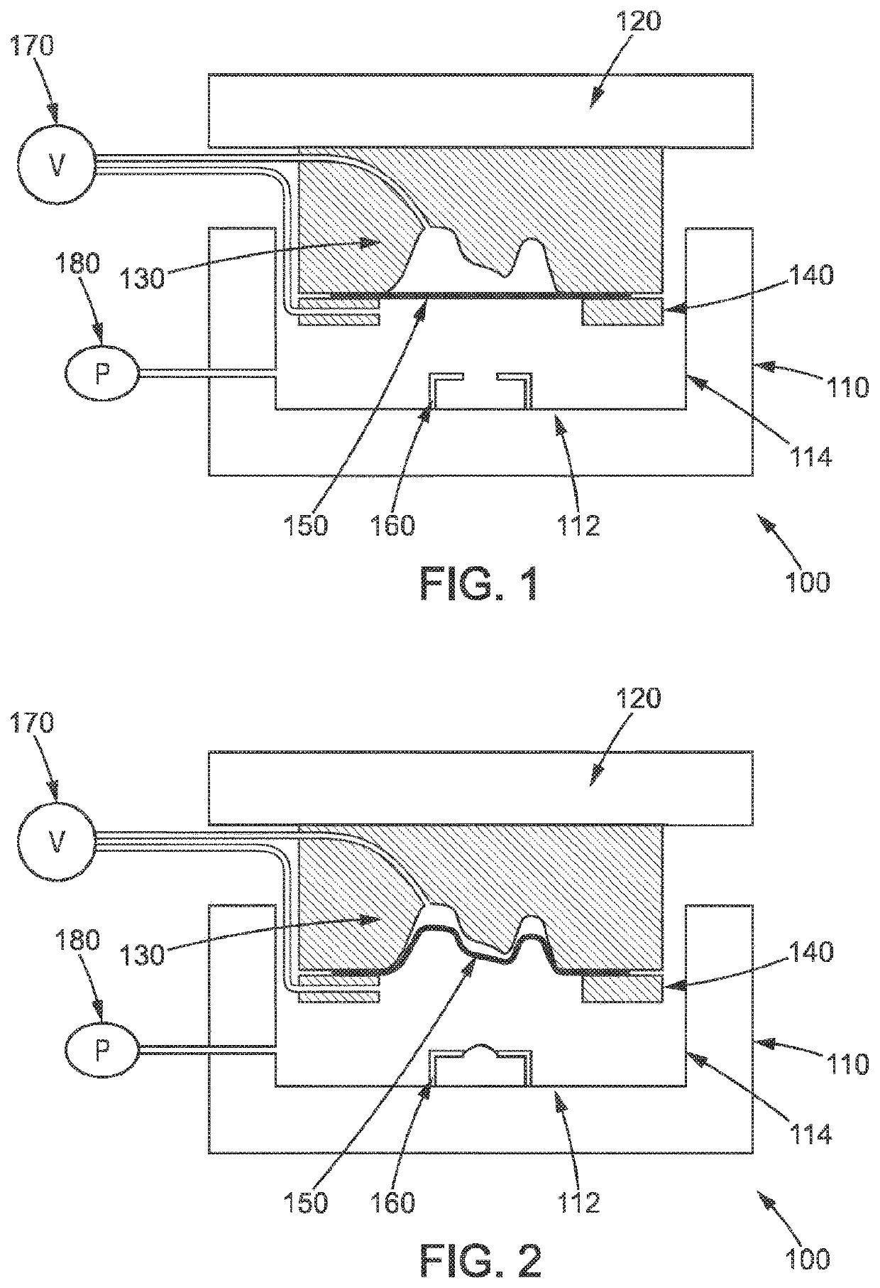
[0047]FIG. 1 shows an electrohydraulic forming device 100 according to a first embodiment. This electrohydraulic forming device 100 comprises a frame 110 and a plate 120 on which a mould 130 is mounted. The plate 120, and thus the mould 130 are capable of moving relative to the frame 110. The plate 120 is mounted on a press rigidly secured to the frame 110.

[0048]A blank of material 150 to be deformed is placed between the mould 130 and a blank holder 140. In the embodiment described here, the blank holder 140 is fixed to the mould 130. The frame 110 comprises a bottom wall 112 and a side wall 114. The bottom wall 112, the side wall 114 and the edges of the blank holder 140 define a cavity intended to be filled with a liquid, for example water. A pumping circuit associated with a pump 180 is used to fill the cavity with liquid. A vacuum pump 170 is used to create a vacuum in the space between the mould 130 and the blank of material 150 to be deformed and inside the cavity, more parti...


PUM

PropertyMeasurementUnit
distanceaaaaaaaaaa
vacuumaaaaaaaaaa
dynamic pressureaaaaaaaaaa

Abstract

A method for electrohydraulically forming a blank of material includes—a blank of material to be deformed is placed between a mould and a blank holder, —a cavity containing electrodes is filled with liquid to a predetermined liquid level, —the blank of material is placed in contact with the liquid in the cavity, —a first electric discharge is generated between at least two electrodes so as to deform the blank of material against the mould, —the mould is brought nearer to the electrodes by moving the mould so as to reduce the distance between the electrodes and the blank of material to be deformed after the first electric discharge has been generated, —at least one other electric discharge is generated between at least two electrodes so as to deform the blank of material against the mould.

Description

BACKGROUND OF THE INVENTION[0001]The present invention relates to an electrohydraulic forming method and an electrohydraulic forming device.PURPOSE AND SUMMARY OF THE INVENTION[0002]Electrohydraulic forming is used to deform a blank of material against a mould by applying a dynamic pressure. For this purpose, an electric discharge is generated between at least two electrodes in a cavity filled with liquid, for example water. An electric arc is thus formed between the two electrodes resulting in an elevated temperature gradient and vaporisation of the liquid. A pressure wave, commonly referred to as a “shock wave”, moves at a high speed and presses the blank of material against the mould. Electrohydraulic forming is particularly advantageous compared to other forming methods since it produces a reduced springback and procures engraving type details and / or sharp edges and / or improved elongations at break on the parts to be formed.[0003]In some cases, in particular when the parts to be...

Claims


Application Information

Patent Timeline
Patent Type & Authority Patents(United States)
IPC IPC(8): B21D26/12B21D26/023B21D26/021B21D26/031
CPCB21D26/12B21D26/021B21D26/023B21D26/031
Inventor AVRILLAUD, GILLESFUZEAU, JULIEN
Owner ADM28 S AR L
Features
  • R&D
  • Intellectual Property
  • Life Sciences
  • Materials
  • Tech Scout
  • Unparalleled Data Quality
  • Higher Quality Content
  • 60% Fewer Hallucinations
Learn More