Speed reducer for industrial robot

Inactive Publication Date: 2006-07-20
YASKAWA DENKI KK
View PDF5 Cites 33 Cited by
  • Summary
  • Abstract
  • Description
  • Claims
  • Application Information

AI Technical Summary

Benefits of technology

[0042]FIG. 10 is a diagram with regard to an effect of re

Problems solved by technology

There is a backlash as one of functions requested for the reduction device.
Although when the backlash is large, the backlash constitutes a factor of deteriorating an operational locus accuracy or a positioning accuracy of a robot.
On the other hand, without any backlash at all, a gear operated in a state of lack of the backlash is subjected to a bending stress larger

Method used


Image

  • Speed reducer for industrial robot
  • Speed reducer for industrial robot
  • Speed reducer for industrial robot

Examples


Embodiment Construction

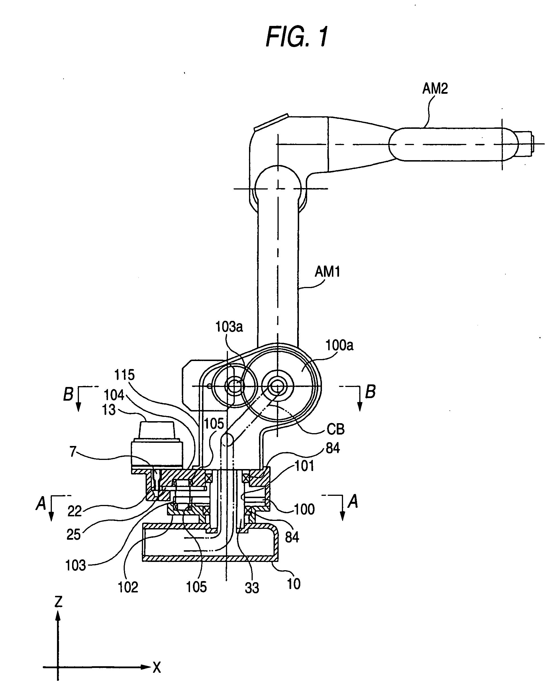
of the invention and is a sectional view taken along a line A-A of FIG. 1.

[0036]FIG. 4 is a view showing Example 2 of the invention and is a sectional view taken along a line B-B of FIG. 1.

[0037]FIG. 5 is an explanatory view with regard to a reduction in a backlash.

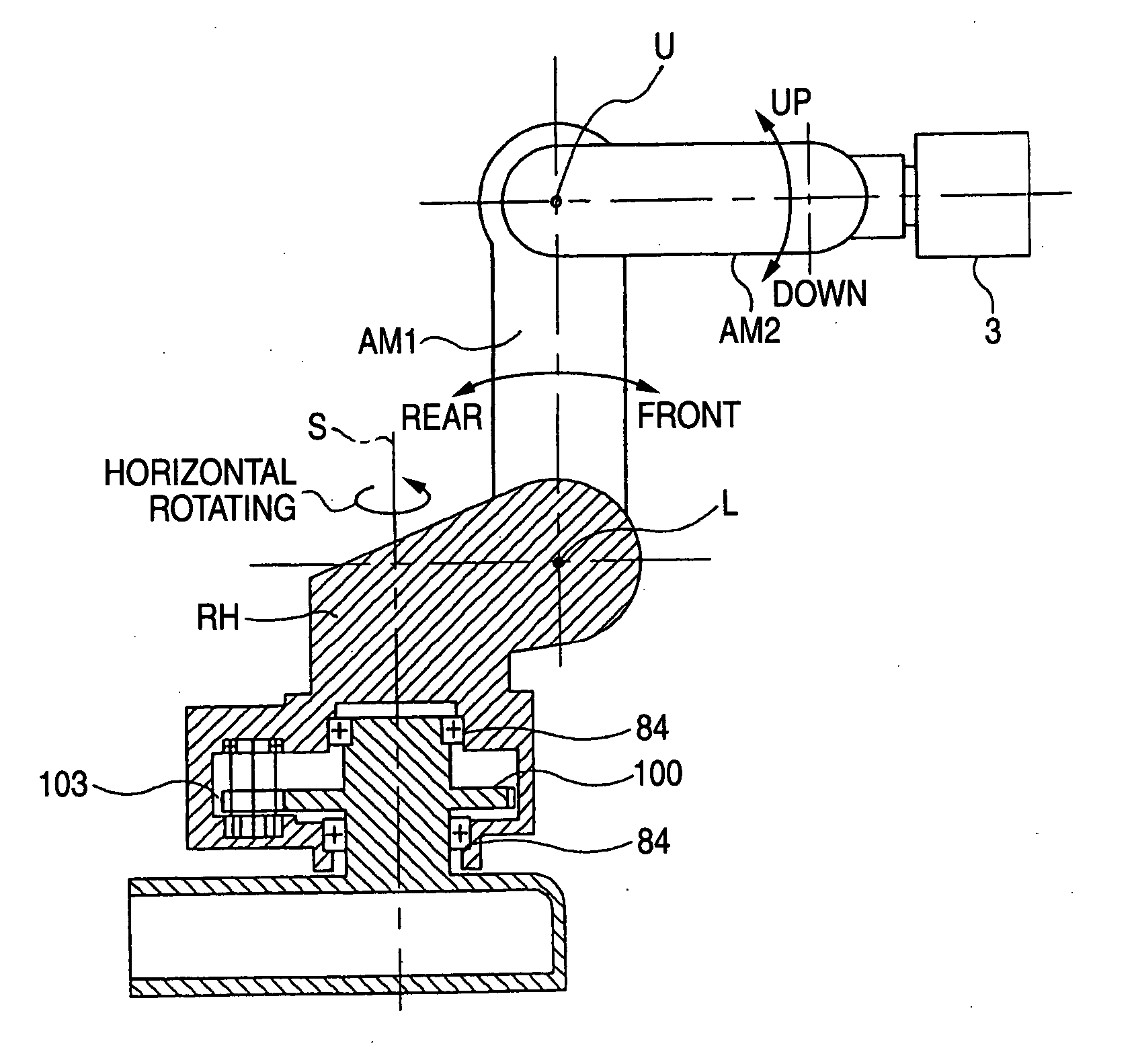
[0038]FIG. 6 is a side view showing a main work area of a robot.

[0039]FIG. 7 illustrates a sectional view (a) with regard to an arrangement of a small gear constituting an object of the invention and a perspective view (b) thereof.

[0040]FIG. 8 is a sectional view of an essential portion according to a reduction device 1 of a background art.

[0041]FIG. 9 is a sectional view according to a reduction device 2 of a background art.

[0042]FIG. 10 is a diagram with regard to an effect of reducing a backlash constituting a problem of the invention.

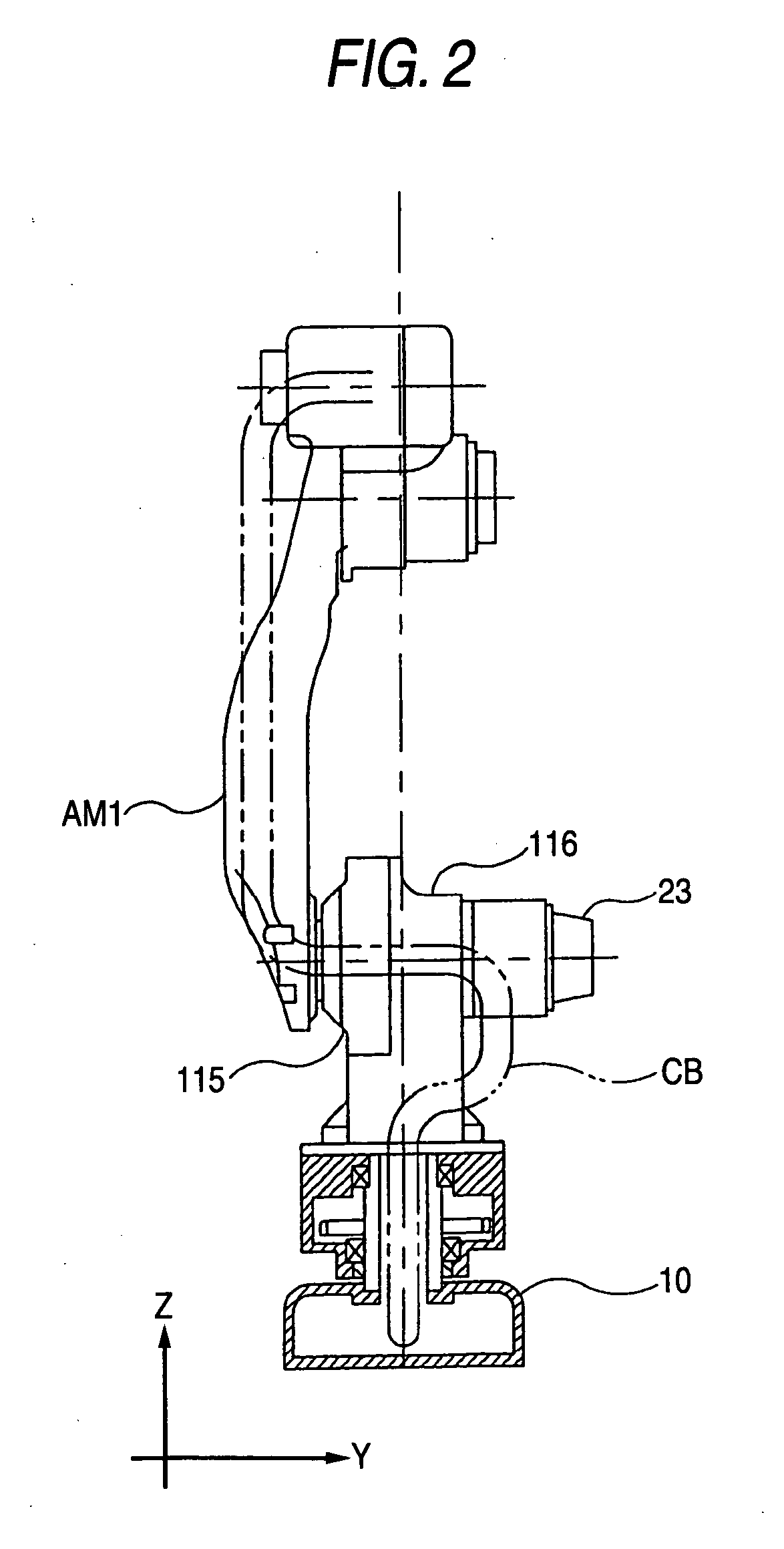
[0043] Further, numerical reference 3 in the drawings designates a load, numerical references 7, 7a designate motor shafts, numerical reference 10 designates a robot base, numerical...


PUM


Abstract

A problem of the invention is to provide a reduction device at low cost capable of considerably alleviating a restriction on a range of operating each shaft of a robot by providing a communication hole at a center portion and wiring a wire-like member therein while using a main bearing having an optimum load capacity. According to the invention, in a reduction device of a rotating shaft (first shaft) having a large gear a position of which is fixed to a robot base and a small gear brought in mesh with the large gear and axially supported in a rotating barrel portion, the large gear and the small gear are arranged at a vicinity of a rotational plane of a second shaft (front/rear shaft), further, in the reduction device of the rotating shaft (first shaft) having a small gear axially supported by a robot base and a large gear which is brought in mesh with the small gear and a position of which is fixed to a rotating barrel portion, a large gear and a small gear are arranged at a vicinity of the rotational plane of the second shaft (front/rear shaft).

Description

TECHNICAL FIELD [0001] The present invention relates to a reduction device of an industrial robot. BACKGROUND ART [0002] In a background art, a joint portion of an industrial robot (hereinafter, referred to as “robot”) is generally attached with a reduction device. There is a backlash as one of functions requested for the reduction device. A backlash refers to an interval between a pinion gear and a spur gear, attached to a shaft of a motor, where strange sound is emitted or friction is produced in case of said interval not optimum. Although when the backlash is large, the backlash constitutes a factor of deteriorating an operational locus accuracy or a positioning accuracy of a robot. On the other hand, without any backlash at all, a gear operated in a state of lack of the backlash is subjected to a bending stress larger than a value conceived in design and it is known that the gear is failed to be broken far earlier than desired service life. It is the most important problem to op...

Claims


Application Information

Patent Timeline
IPC IPC(8): B25J18/00B25J9/10B25J19/00
CPCB25J9/102Y10T74/20317B25J19/0029B25J9/108Y10S901/25
Inventor HANIYA, KAZUHIRO
Owner YASKAWA DENKI KK
Why Eureka
Try Eureka