Two-part, low-backlash spindle nut

a spindle nut, two-part technology, applied in the direction of toothed gearings, belts/chains/gearings, portability lifting, etc., can solve the problems of increasing the overall cost of the spindle nut, and reducing the spring action force during the life of the screw transmission, etc., to achieve simple parts, cost-effective, and simple manufacture and installation.

Active Publication Date: 2008-03-04
EICHENBERGER GEWINDE
View PDF9 Cites 4 Cited by
  • Summary
  • Abstract
  • Description
  • Claims
  • Application Information

AI Technical Summary

Benefits of technology

[0006]The present invention is to develop a low-backlash spindle nut of the type mentioned at the outset which allows simple manufacture and installation, comprises simple parts, does not change its properties during the life of the screw transmission, is cost-effective and does not have any interfering, projecting parts.
[0007]A two-part, low-backlash spindle nut embodied according to the invention includes bodies of the nut parts turned towards one another having with at least two opposed bores arranged in an offset manner. A coil spring contacts holding regions of each of the opposed offset bores. The coil spring is inserted with a bending load acting crosswise to its longitudinal direction. The two-part, low-backlash spindle nut, allows for both nut parts to be manufactured simply with axially parallel bores. Coil springs curved crosswise to their longitudinal direction are inserted into the opposed offset bores lying in the bodies of the nut parts such that simple installation is ensured. The holding region of the bore can be understood as the area of the bore surrounding the end area of the coil spring with low backlash. In particular, the end area of the coil spring is held at the above location, such that the holding region lies in the base region of the bore which generally is formed by a blind-hole bore. Thus, an external cover of the spindle nut is not necessary, since the coil springs are externally protected in the bodies of the nut parts. Moreover, subjecting the coil springs to a bending load crosswise to their longitudinal direction for preloading the nut parts with torsion provides an advantage over the prior art. In particular, the action of force of the coil spring on the two nut parts remains virtually constant over the entire life of the screw transmission. This measure leads to a particularly higher durability of the screw transmission.
[0008]An advantage of the instant invention is the structural arrangement of the coil spring having a smaller external diameter in the region of the openings of the bores than the bore itself. In particular, this shaping of the coil spring allows a bending of the coil spring crosswise to its longitudinal direction in the opening region of the bores.
[0009]At their openings, the cylindrical bores can be provided with recesses allowing the lateral bending of the coil spring crosswise to its longitudinal direction. In particular, the opening regions of the bores can easily be provided with recesses during manufacture. With the above structural arrangement, the coil spring can advantageously include a cylindrical outer surface in its entire length.
[0015]The instant invention is directed to a low backlash spindle nut comprising a first part and a second part having internal threads for interaction with an external thread of a spindle, and at least one spring causing a torsional force between the first and second parts. The torsional force rotates the first and second parts to push against one another, and compensates for wear on the internal and external threads.

Problems solved by technology

The installation of this spindle nut entails considerable effort.
The spring interferes on the surface of the nut parts requiring a protective cover, which increases the overall costs of the spindle nut.
However, the action of force of the spring will decrease during the life of the screw transmission, because the spring slackens due to stretching caused by thread wear.

Method used


Image

  • Two-part, low-backlash spindle nut
  • Two-part, low-backlash spindle nut
  • Two-part, low-backlash spindle nut

Examples


Embodiment Construction

[0023]The particulars shown herein are by way of example and for purposes of illustrative discussion of the embodiments of the present invention only and are presented in the cause of providing what is believed to be the most useful and readily understood description of the principles and conceptual aspects of the present invention. In this regard, no attempt is made to show structural details of the present invention in more detail than is necessary for the fundamental understanding of the present invention, the description taken with the drawings making apparent to those skilled in the art how the several forms of the present invention may be embodied in practice.

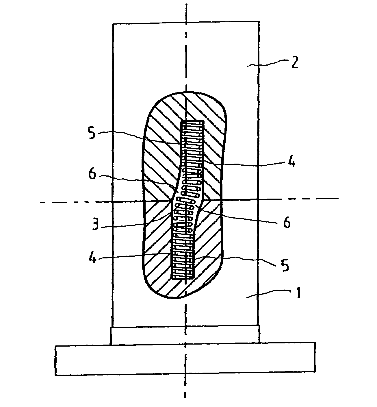
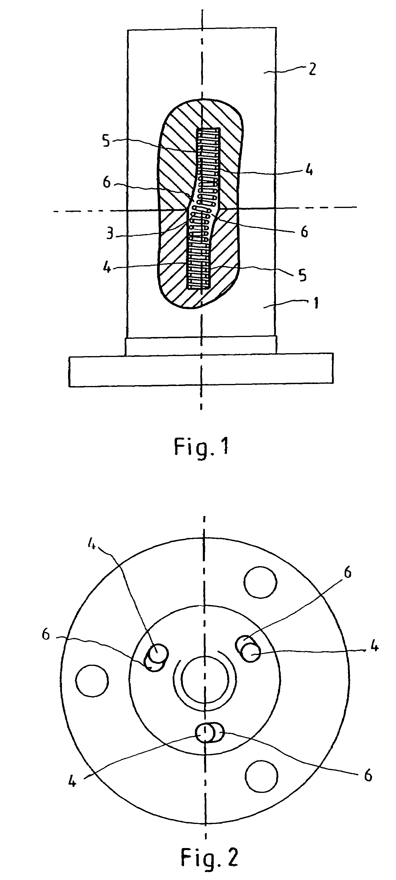
[0024]FIG. 1 shows a two-part spindle nut partially in section. This spindle nut is composed of two nut parts 1 and 2. The two-part spindle nut is for a screw transmission. The spindle of the screw transmission (not shown) has an external thread, which is known per se. The two nut parts 1 and 2 are equipped with internal ...


PUM


Abstract

Apparatus for screw transmission on a spindle comprising a nut having at least a first and second part with internal threads, at least one bore in the first and second parts, and at least one spring located within the at least one bore of the first and second parts and arranged with a bending load acting crosswise to a longitudinal direction of the bore. The instant abstract is neither intended to define the invention disclosed in this specification nor intended to limit the scope of the invention in any way.

Description

CROSS-REFERENCE TO RELATED APPLICATIONS[0001]The present application claims priority under 35 U.S.C. §119 of Swiss Patent Application No. 01354 / 04, filed on Aug. 17, 2004, the disclosure of which is expressly incorporated by reference herein in its entirety.BACKGROUND OF THE INVENTION[0002]1. Field of the Invention[0003]The present invention relates to a two-part, low-backlash spindle nut for a screw transmission with two nut parts equipped with internal threads that interact with the external thread of the spindle of the screw transmission. The two nut parts on the spindle are loaded directed towards one another by at least one spring by torsion.[0004]2. Discussion of Background Information[0005]U.S. Pat. No. 4,433,590 shows a two-part spindle nut including two nut parts provided with internal threads preloaded on the external thread of the spindle by a spring, such that the nut parts are held against one another by a preloaded torque from the spring. The spring is wound on the cyl...

Claims


Application Information

Patent Timeline
Patent Type & Authority Patents(United States)
IPC IPC(8): F16H3/06F16H29/02F16H55/18F16H29/20F16H27/02
CPCF16H25/2006Y10T74/18728Y10T74/19902
Inventor HUSISTEIN, KURT
Owner EICHENBERGER GEWINDE
Why Eureka
Try Eureka