Edge-locking type tubular belt conveyer

A tubular belt and conveyor technology, used in conveyors, conveyor objects, transportation and packaging, etc., can solve the problems of low running resistance and low system energy consumption.

Inactive Publication Date: 2007-10-17
裴志胜
View PDF0 Cites 16 Cited by
  • Summary
  • Abstract
  • Description
  • Claims
  • Application Information

AI Technical Summary

Problems solved by technology

[0010] The purpose of the present invention is to solve many existing problems at present, and to provide a new type of low running resistance, low system energy consumption, no material leaka...

Method used


Image

  • Edge-locking type tubular belt conveyer
  • Edge-locking type tubular belt conveyer
  • Edge-locking type tubular belt conveyer

Examples


Embodiment Construction

[0027] Below in conjunction with accompanying drawing, the present invention and concrete implementation will be further described:

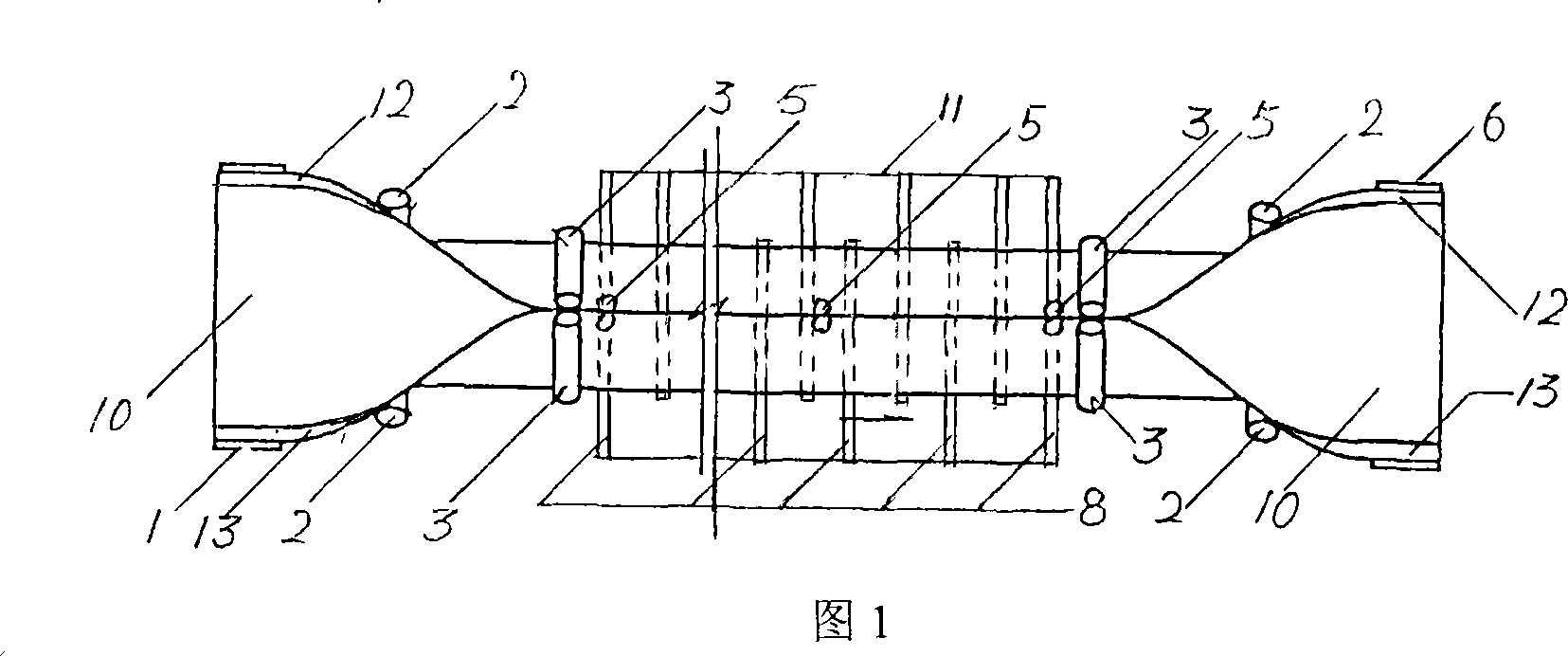
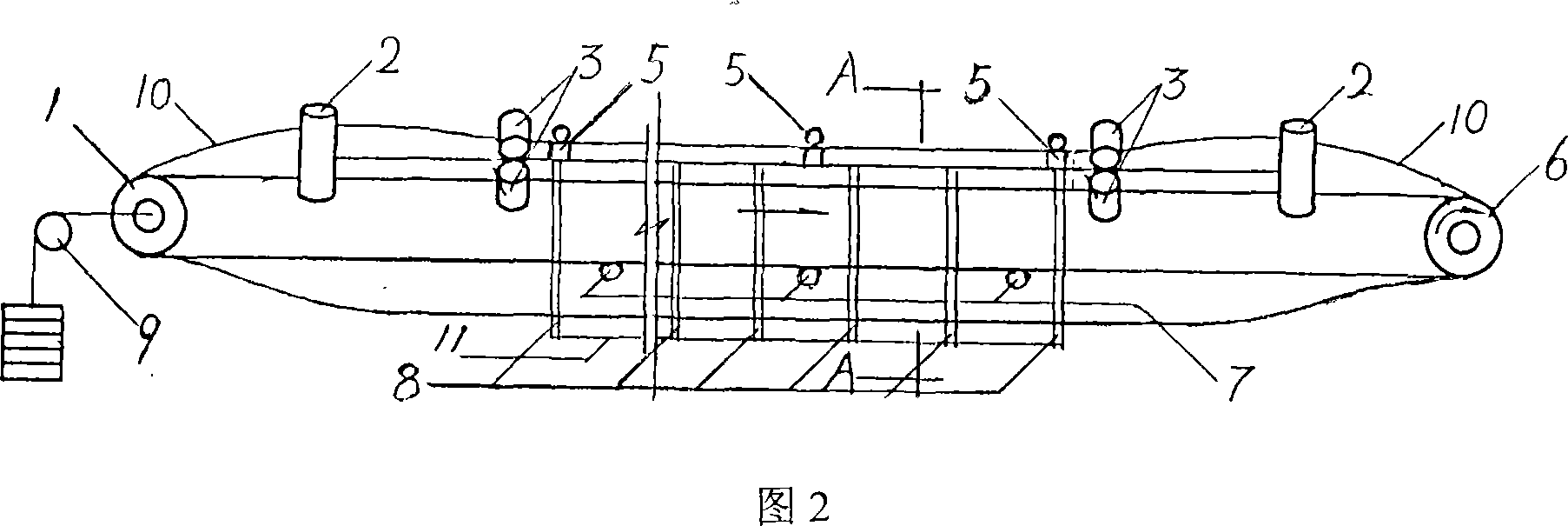
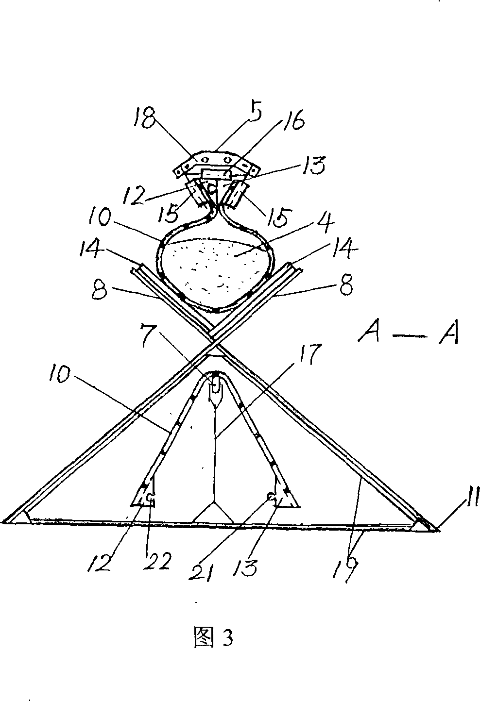
[0028] Referring to the accompanying drawings, the drive drum (6) and the tail drum (1) are covered with an expanded endless conveyor belt (10), the conveyor belt (10) is tensioned by the tensioning device (9), and the driving device is connected to the drive drum (6). ) is driven to realize the circular rotation of the conveyor belt (10), the material (4) is wrapped in the tube-shaped conveyor belt (10) in the bearing section, and the wrapping and unwrapping are started by the guide roller (2) and the tube support Roller (3) realizes.

[0029] After the material is wrapped, the pipe seam rolled into the conveying pipe is formed by the upper male and female rails (21, 22) of the male and female strips (13, 12) of the zipper that are consolidated on the two sides of the conveyor belt (10). Locking to achieve the purpose of connection, the number...


PUM


Abstract

In transportation mechanism field, cannular belt conveyer is preferred, but exist technology has large resistance, high cost and bad reliability due to inappropriate scheme, thereby, the invention provides a new conveyor which includes a drive device, a roller, a tension device, a support roller, a rolling guider, a conveying belt, a slide fastener and a frame. The conveying belt coils to pipe-shape, pipe sew is locked by the slide fastener and raises a track, the track is controlled by the rolling guider to realize control for the conveying pipe, a bearing belt is equipped on the opening support roller, a supporting belt is arranged on a point supporting type supporting wheel transportation path, and the transportation path is disposed on the module type frame. Advantages of the invention are: running resistance is small, manufacture is simple, cost is low, a great deal of material can be fast transmitted on varies landform for a long distance, and the conveyor incorporates supporting, guiding, carrying and hanging.

Description

technical field [0001] The invention belongs to the category of conveying machinery, in particular to an overlock type tubular belt conveyor. Background technique [0002] The technology of rolling the conveyor belt of the ordinary belt conveyor into a circular tube and keeping it running in the two transmission compartments composed of circular idler rollers was first applied for by the Japanese in China, and it was named tubular belt conveyor. Machine (Patent No. 870106863, 871044332.7). Because this kind of method has caused the huge increase of transmission resistance, someone changed the conveyor belt in the return section to flat roller support, and the carrier belt continued to be hooped in the transmission cabin formed by the round roller group (Chinese Patent Application No. 2003100014.2, Publication date May 21, 2003). Even so, it still cannot change a series of problems caused by the improper method of forming a round idler group in the original scheme, which is...

Claims


Application Information

Patent Timeline
IPC IPC(8): B65G15/08B65G15/60B65G39/12B65G15/30B65G45/10
Inventor 裴志胜裴春光
Owner 裴志胜
Why Eureka
Try Eureka