

Liquid crystal display device
A technology of liquid crystal display device and liquid crystal panel, which is applied in nonlinear optics, instruments, optics, etc. It can solve the problems of improper assembly of the front frame and the back panel, so as to reduce the lack of tightness or looseness after the engagement, and improve the resistance Impact ability, the effect of reducing the reserved gap
- Summary
- Abstract
- Description
- Claims
- Application Information
AI Technical Summary
Problems solved by technology
Method used
Image

Examples
Embodiment 1
[0042] For more concise and convenient description, the same symbols and names are used in Embodiment 1 of the present invention for the same components as the snap fasteners in the prior art.
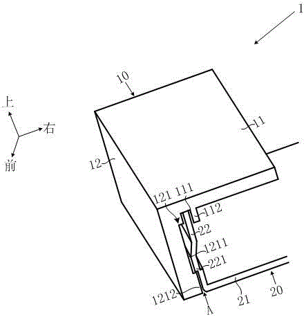
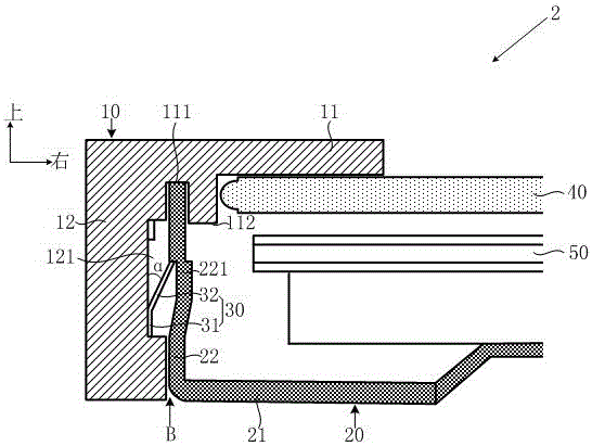
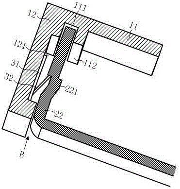
[0043] Such as figure 2 and image 3As shown, a liquid crystal display device 2 provided by the embodiment of the present invention includes a front frame 10, a liquid crystal panel 40, a backlight assembly 50, and a back plate 20 that are sequentially installed together, wherein: the front frame 10 includes a 40, the snap arm 11 on the upper surface and the side wall 12 extending vertically from the side of the snap arm 11, the inner surface of the side wall 12 is provided with a fixing groove 121; The side of the connecting wall 22 extends vertically. The connecting wall 22 defines a limiting groove 222 , and the opening of the limiting groove 222 is located on the outer surface of the connecting wall 22 .
[0044] Between the front frame 10 and the back plate 20 of the liquid cry...
Embodiment 2
[0067] In order to describe more concisely and conveniently, the same components as those in the first embodiment also use the same signs and names in the second embodiment, and the specific description of the corresponding components is omitted.
[0068] The independent bracket in the first embodiment is directly placed on the front frame, but the independent bracket can also be connected to the fixing groove of the front frame by mechanical connection or glue, wherein the mechanical connection includes but not limited to the use of clips or screws and Limiting structures such as screw fit or fixed column.
[0069] Specifically, such as Figure 7 As shown, in the second embodiment, the inward opening angle α=70° formed by the first part 31 and the second part 32 of the independent bracket 30 is illustrated by a threaded fixing method. Since the bracket 30 adopts a thinner metal sheet, Therefore, considering the convenience of processing, four circular perforations 33 are add...
PUM
 Abstract
Description
Claims
Application Information