
A method for controlling the trajectory while drilling a horizontal well in thin-bed shale oil

A technology for trajectory control and horizontal wells, applied in the field of oil exploration, to achieve the effect of increasing the drilling rate of oil layers and optimizing the trajectory while drilling

Active Publication Date: 2022-05-20
PETROCHINA CO LTD
View PDF23 Cites 0 Cited by
  • Summary
  • Abstract
  • Description
  • Claims
  • Application Information

AI Technical Summary

Problems solved by technology

[0003] The purpose of the present invention is to provide a thin-bed shale oil horizontal well trajectory control method while drilling in order to solve the above problems, which solves the current existing problems

Method used


Image

  • A method for controlling the trajectory while drilling a horizontal well in thin-bed shale oil
  • A method for controlling the trajectory while drilling a horizontal well in thin-bed shale oil
  • A method for controlling the trajectory while drilling a horizontal well in thin-bed shale oil

Examples


no. 1 example

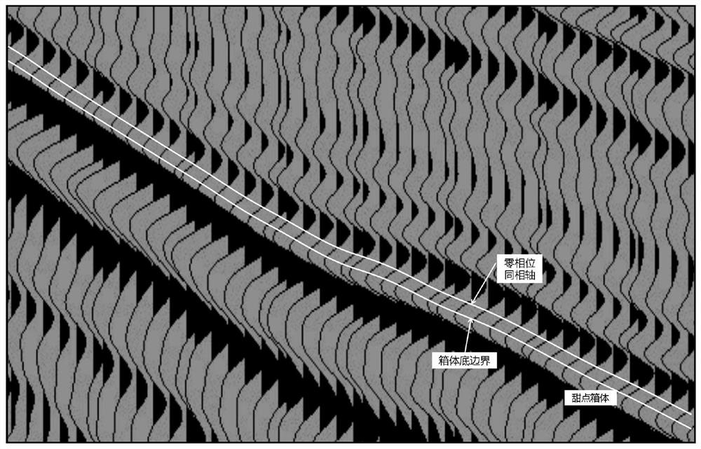
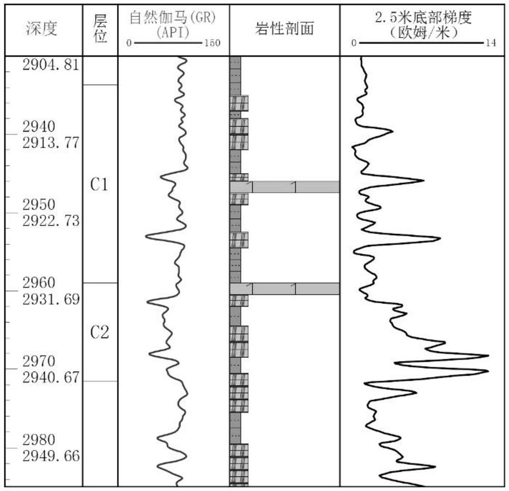
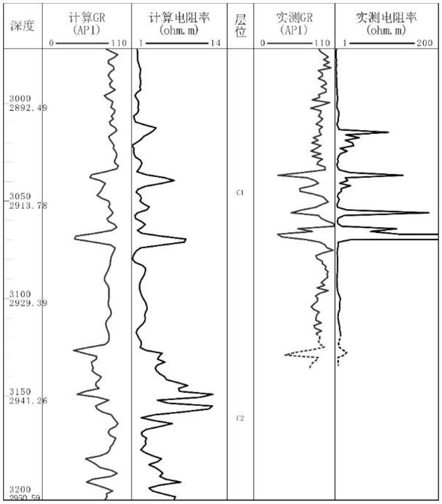
[0053] The first embodiment: as Figure 1-7 As shown, the present embodiment adopts the following technical scheme: a method for controlling the trajectory while drilling a thin-bed shale oil horizontal well, comprising the following steps:

[0054] 1) Determine the optimal artificially synthesized seismic trace, and generate the seismic sweet spot time window according to the seismic velocity of the sweet spot section of the horizontal well;

[0055] 2) Establish the standard logging response curve of the sweet spot section by using the corresponding shape of the well logging curve of the known well, and generate the predicted logging curve according to the design trajectory of the shale oil horizontal well;

[0056] 3) During the process of drilling, adjust the trajectory while drilling in time according to the real-time logging curve and refer to the logging absolute value and variation range of the marked interval.

[0057] Wherein, in the step 1), the optimal artificiall...

no. 2 example

[0090] 1) Determine the optimal synthetic seismic trace, and generate the seismic sweet spot time window according to the seismic velocity of the horizontal well sweet spot section.

[0091] ① Well seismic calibration for all intervals.

[0092] a. Determine the optimal synthetic seismic trace.

[0093] G 1 , G 2and G 3 There are 3 geological stratifications in total, and the seismic traces are artificially synthesized using the acoustic time difference logging curve AC and the corresponding time depth is G t1 , G t2 and G tn , the seismic interpretation interface is numbered T from top to bottom corresponding to the time and depth 1 , T 2 and T n , as attached figure 1 -A shown.

[0094] Define the well-seismic fit degree DF formula:

[0095] Among them, G t1 , G t2 ,...,G tn is the time depth corresponding to the synthetic seismic trace, T 1 , T 2 ,...,T n Interpret interfaces for seismicity corresponding to time-depth.

[0096] Search the minimum value o...


PUM


Abstract

The invention discloses a thin-bed shale oil horizontal well drilling trajectory control method, comprising the following steps: 1) determining the optimal artificially synthesized seismic trace, and generating a seismic sweet spot time window according to the seismic velocity of the sweet spot section of the horizontal well; 2) using known Establish the standard logging response curve of the sweet spot section according to the corresponding shape of the well logging curve, and generate the predicted logging curve according to the design trajectory of the shale oil horizontal well; The beneficial effects of the present invention are as follows: 1) In the case of human intervention, a more accurate time-depth relationship is established; 2) On the basis of the establishment of the time-depth relationship, the seismic profile where the top and bottom of the sweet spot is calculated position, determine the sweet spot time window, and optimize the trajectory while drilling by projecting the position of the drill bit in real time during the drilling process; 3) establish the standard logging curve of the formation in this area by using known wells and formation dips, adjust the trajectory in time, and increase the drilling rate of oil layers .

Description

Technical field: [0001] The invention relates to the technical field of petroleum exploration, in particular to the technical field of a method for controlling the trajectory while drilling a thin-bed shale oil horizontal well. Background technique: [0002] The vertical thickness of the marine shale oil sweet spot is generally between 20 and 90 m, the plane distribution is stable, and the formation occurrence is stable, which is suitable for large-scale development of horizontal wells. my country's oil-bearing basins are dominated by continental lake basins, and the spatial distribution stability of continental shale oil sweet spots is relatively poor. The vertical thickness is generally between 6 and 15 m, and the plane distribution has an obvious thickness center. The thickness of sweet spots is thin and changes rapidly. , the plane distribution stability is poor, which brings difficulties to how to accurately control the well trajectory to continuously drill in the sweet ...

Claims


Application Information

Patent Timeline
Patent Type & Authority Patents(China)
IPC IPC(8): E21B47/12E21B49/00
CPCE21B47/12E21B49/00
Inventor 周立宏肖敦清韩国猛马建英杨飞范军侠石倩茹陈双清周可佳王昌丽付东立梁晨尹玲玲孟立娜周素彦
Owner PETROCHINA CO LTD
Learn More