
Force-transmitting structure and its construction method of post-cast belt on foundation pit floor

A construction method and post-casting belt technology, which can be used in infrastructure engineering, excavation, construction, etc., and can solve problems such as foundation pit collapse and ineffective transmission.

Active Publication Date: 2021-05-14
CHINA MCC20 GRP CORP
View PDF7 Cites 0 Cited by
  • Summary
  • Abstract
  • Description
  • Claims
  • Application Information

AI Technical Summary

Problems solved by technology

It cannot effectively transmit and resist the external force on the enclosure structure. After the support is removed, it will have a destructive effect on the bottom plate and the enclosure structure, which may cause accidents such as the collapse of the foundation pit

Method used


Image

  • Force-transmitting structure and its construction method of post-cast belt on foundation pit floor
  • Force-transmitting structure and its construction method of post-cast belt on foundation pit floor
  • Force-transmitting structure and its construction method of post-cast belt on foundation pit floor

Examples


Embodiment 1

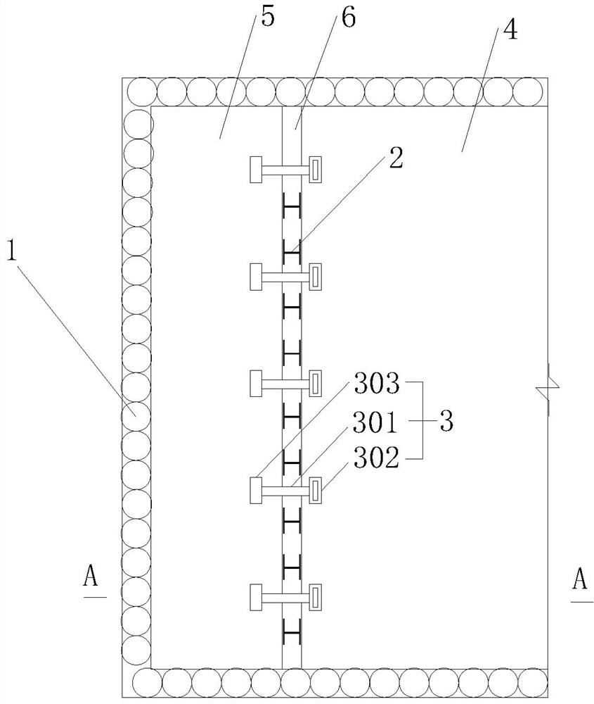
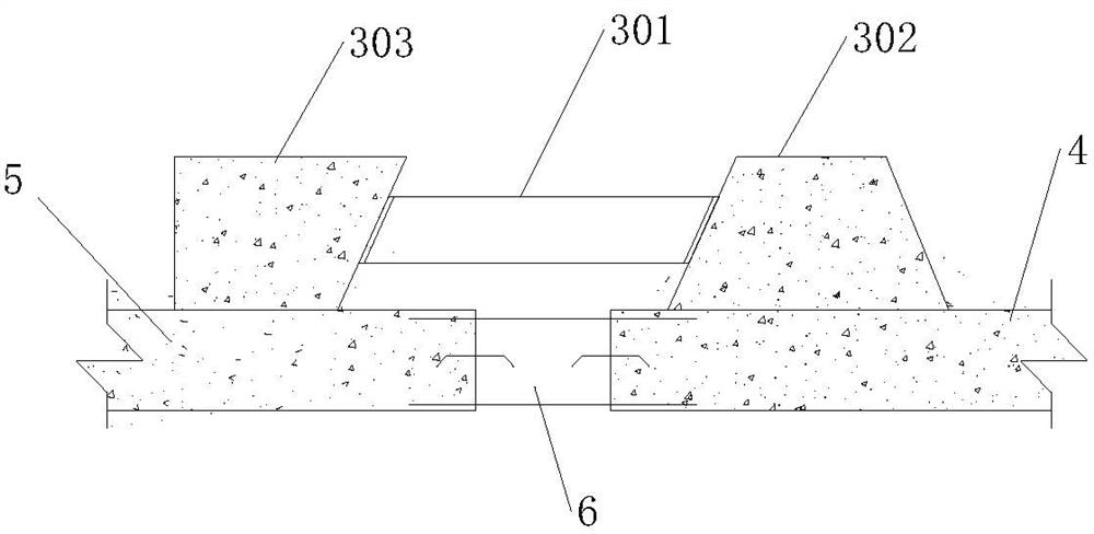
[0034] A post-casting belt force transmission structure for foundation pit floor, such as figure 1 and figure 2 shown, including:

[0035] A plurality of first steel members 2 arranged along the extension direction of the back-casting belt 6 are sandwiched between the bottom plates on both sides of the back-casting belt 6, and between the first bottom plate 4 and the second bottom plate 5. The two ends of the member 2 are respectively fully fitted with the end faces of the first base plate 4 and the second base plate 5 to ensure uniform force transmission; the height of the first steel member 2 should be less than the height of the post-casting belt 6, and the reserved steel bars shall prevail. The first steel member 2 can be made of I-beam, H-shaped steel or assembled and welded with steel plates; Calculation OK.

[0036] The plurality of corbel force transmission units 3 arranged along the extension direction of the back casting belt 6 include: a first corbel 302 fixed o...

Embodiment 2

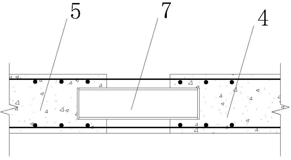
[0050] Embodiment 2 is a further improvement of Embodiment 1 to further enhance the stability of the horizontal force transmission structure of the bottom plate. On the basis of Example 1, as image 3 As shown, a plurality of second steel members 7 are distributed along the extension direction of the post-casting belt 6 , and both ends of the second steel members 7 are buried in the concrete of the bottom plates on both sides of the post-casting belt 6 . The second steel member 7 can be I-shaped steel, H-shaped steel or assembled and welded with steel plates.

Embodiment 3

[0052] Embodiment 3 is a further improvement of Embodiment 1 to further enhance the stability of the horizontal force transmission structure of the bottom plate. On the basis of Example 1, as Figure 4 As shown, at the post-casting belt 6 position, at least one reinforcing bar 9 is welded and fixed on the main reinforcement 8 of the bottom plate on both sides of the post-casting belt 6 , and the reinforcing steel bar is arranged in the same direction as the main rib 8 .

[0053] Further, a reinforcement bar 9 is fixed on both sides of the main bar 8, and the diameter of the reinforcement bar 9 is the same as that of the main bar 8, and its length is more than 1 m. Preferably, a reinforcement bar 9 with a length of 2 m is selected.

[0054] In an optional implementation of this embodiment, a plurality of second steel members 7 are also distributed along the extension direction of the post-cast belt 6, and the two ends of the second steel members 7 are embedded in the concrete o...


PUM


Abstract

The invention provides a post-casting belt force transmission structure for foundation pit floor and its construction method, wherein the force transmission structure includes: a plurality of first steel members arranged along the extension direction of the post-casting belt, which are sandwiched in the post-casting belt Between the bottom plates on both sides; a plurality of corbel force transmission units arranged along the extending direction of the post-casting belt, which include: two corbels and a support member, and the two corbels are respectively fixed on both sides of the post-casting belt The upper surface of the bottom plate, the support is horizontally supported between the two corbels. The post-cast belt force transmission structure and construction method of the foundation pit bottom plate provided by the present invention can effectively solve the problems of insufficient strength of the small-block bottom plate in the foundation pit project and the ineffective force transmission of the post-cast belt; ensure the safety of the foundation pit, and the poured bottom plate does not affected and damaged; the present invention can reduce the division of the bottom plate under the premise of ensuring the safety of the foundation pit, without affecting the construction of the upper structure to the greatest extent.

Description

technical field [0001] The invention relates to the technical field of building construction, in particular to a post-casting belt force transmission structure of a foundation pit floor and a construction method thereof. Background technique [0002] In the excavation and construction of underground structures in soft soil areas, it is often necessary to take supporting measures on the side of the foundation pit to ensure that the soil outside the foundation pit does not deform and slip into the foundation pit. When the buried depth of the basement is large or the surrounding conditions of the foundation pit are complex and sensitive to soil deformation, the support method of internal support plus cast-in-place piles around the pit or continuous wall is often adopted. During excavation construction, the supporting structure shall be constructed according to the supporting structure design requirements. Then, when the main body of the basement structure starts to be construct...

Claims


Application Information

Patent Timeline
Patent Type & Authority Patents(China)
IPC IPC(8): E02D17/02E02D17/04
CPCE02D17/02E02D17/04
Inventor 施群凯陶荣江张雄
Owner CHINA MCC20 GRP CORP
Learn More