Conveniently detached chemical centrifugal pump

A centrifugal pump and chemical technology, applied in the field of detachable chemical centrifugal pump, can solve the problems of manpower, accidents, danger, etc., and achieve the effect of easy disassembly

Inactive Publication Date: 2019-08-16
QUZHOU SHUNAN ELECTRONICS COMMERCE CO LTD
View PDF4 Cites 0 Cited by
  • Summary
  • Abstract
  • Description
  • Claims
  • Application Information

AI Technical Summary

Problems solved by technology

[0002] The installation of traditional chemical centrifugal pumps is mostly fixed by screws or rivets. The rotating screws need to be tightened manually. Once the screws are not tightened, accidents and dangers are likely to occur when the motor rotates at high speed during the work process. Therefore, the instability of manual operation is high. , it takes a lot of manpower to disassemble and install at the same time, and it is troublesome

Method used


Image

  • Conveniently detached chemical centrifugal pump
  • Conveniently detached chemical centrifugal pump
  • Conveniently detached chemical centrifugal pump

Examples


Embodiment Construction

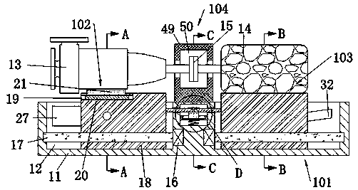
[0022] Combine below Figure 1-Figure 6 The present invention is described in detail, and for convenience of description, the orientations mentioned below are now stipulated as follows: figure 1 The up, down, left, right, front and back directions of the projection relationship itself are the same.

[0023] The present invention relates to a detachable chemical centrifugal pump, which is mainly used for fixing and splicing when installing and disassembling the chemical centrifugal pump. The present invention will be further described below in conjunction with the drawings of the present invention:

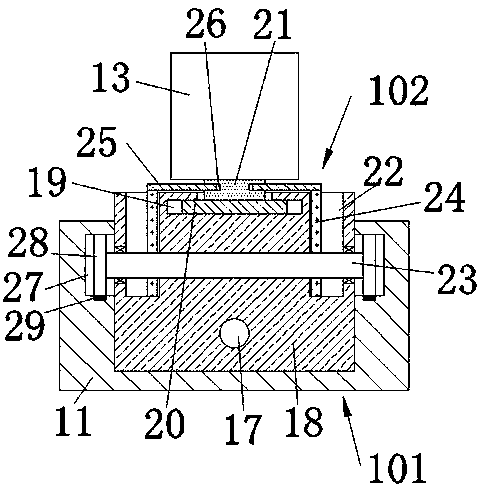
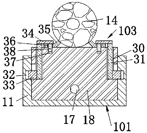
[0024] A detachable chemical centrifugal pump according to the present invention includes a base 11, and a moving cavity 12 with an upward opening is arranged symmetrically in the left and right sides of the base 11, and a moving device 101 is arranged in the moving cavity 12. The upper side of the moving device 101 is provided with a pump body 13, and the upper side of the moving...


PUM


Abstract

The invention discloses a conveniently detached chemical centrifugal pump which comprises a base. Moving cavities opened upward are symmetrically formed left and right in the base, a moving device isarranged in each moving cavity, a pump body is arranged on one side of the moving device on the left side, a working motor is arranged on the upper side of the moving device on the right side, and themoving devices can control the pump body and the working motor to move, separately, to further connect and detach the pump body and the working motor. By fixing and moving the centrifugal pump and the working motor automatically, separately, power connection of the centrifugal pump and the working motor is achieved. Meanwhile, one of the centrifugal pump and the working motor is detached independently. The centrifugal pump can be fixed or detached while being moved, so that the centrifugal pump is faster and more convenient.

Description

technical field [0001] The invention relates to the technical field of chemical centrifugal pumps, in particular to a detachable chemical centrifugal pump. Background technique [0002] The installation of traditional chemical centrifugal pumps is mostly fixed by screws or rivets. The rotating screws need to be tightened manually. Once the screws are not tightened, accidents and dangers are likely to occur when the motor rotates at high speed during the work process. Therefore, the instability of manual operation is high. , It takes a lot of manpower to disassemble and install at the same time, and it is troublesome. The present invention illustrates a device capable of solving the above-mentioned problems. Contents of the invention [0003] technical problem: [0004] Traditional chemical centrifugal pumps are fixed by screws, and the splicing and fixing are all manual operations, and disassembly and installation are extremely troublesome. [0005] In order to solve th...

Claims


Application Information

Patent Timeline
Patent Type & Authority Applications(China)
IPC IPC(8): F04D1/00F04D13/06F04D29/62H02K5/26
CPCF04D1/00F04D13/06F04D29/628H02K5/26
Inventor 屠诗媛
Owner QUZHOU SHUNAN ELECTRONICS COMMERCE CO LTD
Why Eureka
Try Eureka