
Surgical guide for positioning a resurfacing head implant

A technology of guidance system and implantation device, which is applied in the field of patient-specific head guidance for head replacement, and can solve problems such as difficult to visualize landmark orientation

Active Publication Date: 2019-08-16
EMBODY ORTHOPAEDIC
View PDF6 Cites 1 Cited by
  • Summary
  • Abstract
  • Description
  • Claims
  • Application Information

AI Technical Summary

Problems solved by technology

This can be misleading when locating implant components
Additionally, the surgeon has limited access and field of view during surgery, making it difficult to visualize landmarks and judge bone orientation

Method used


Image

  • Surgical guide for positioning a resurfacing head implant
  • Surgical guide for positioning a resurfacing head implant
  • Surgical guide for positioning a resurfacing head implant

Examples


Embodiment Construction

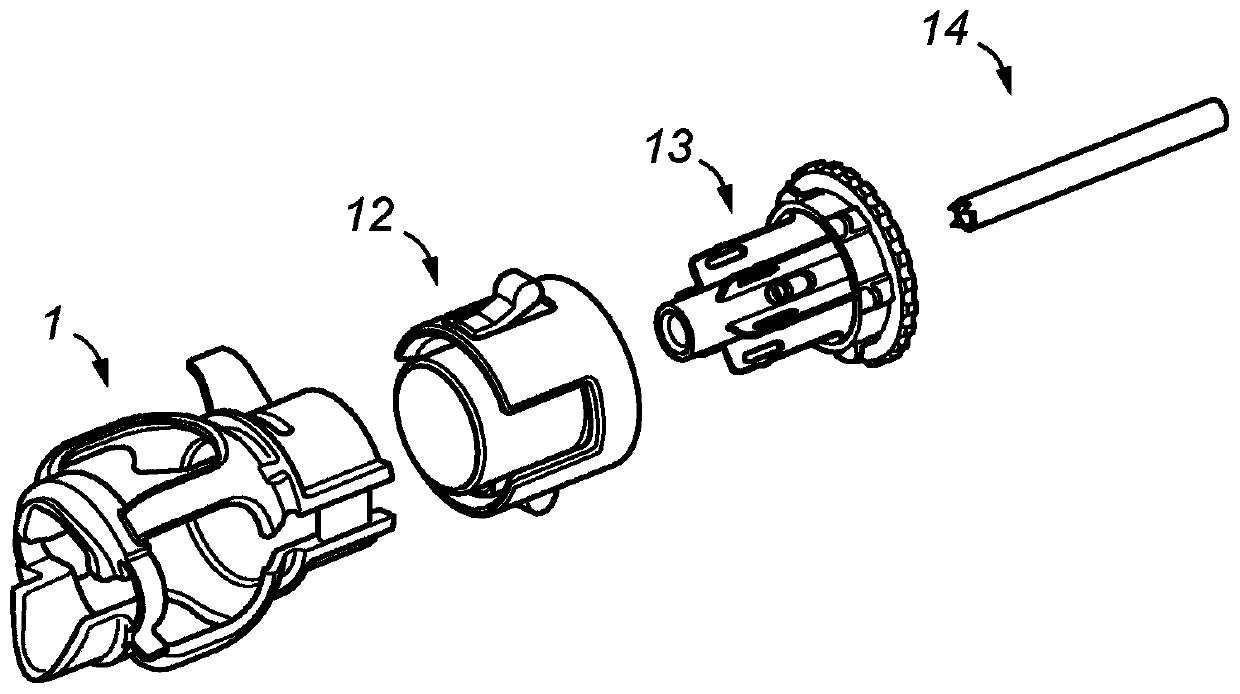
[0145] will now refer to Figure 1 to Figure 5 Describe patient-specific head guides.

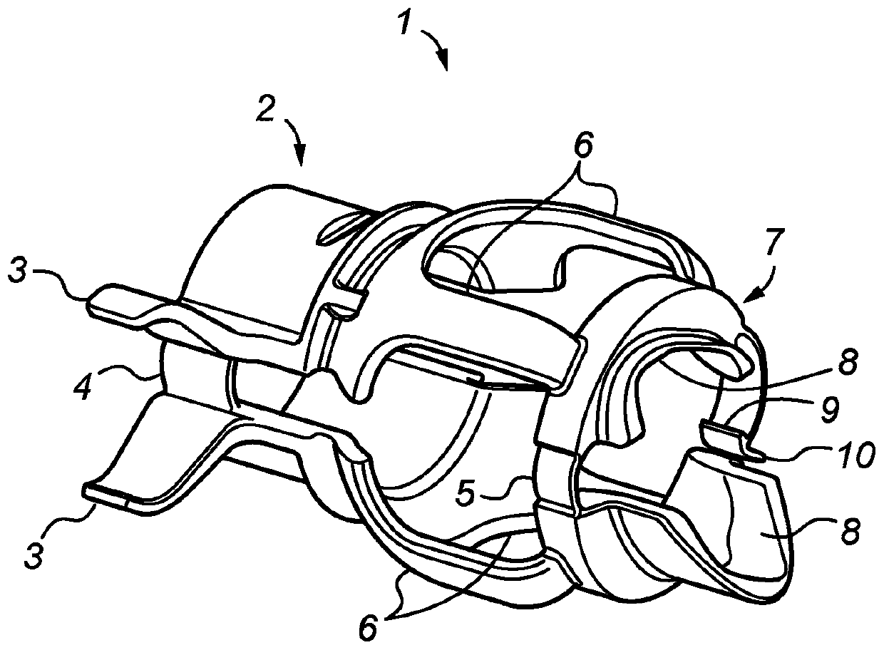
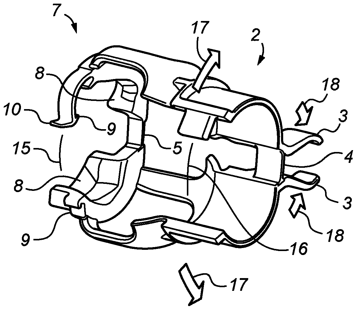
[0146] exist figure 1 As can be seen in the figure, the main body [1] is manufactured as a single part consisting of two approximately cylindrical rings, with a cylindrical ring at each end of the part, and a plurality of connecting struts [6] (such as two one, four or six pillars). One ring (neck ring [7]) is positioned around the femoral neck and the other ring (head ring [2]) is positioned on the opposite side of the femoral head. The neck ring [7] has an integral hinge [5] on one side and an opening [15] on the other side. The headband [2] has an integral hinge [4] on one side and an opening [16] on the other side. The two hinges are arranged in axial alignment so that they act together (similar to two hinges on a door or gate). The headband has two blade features [3] that extend outward to the other side of the hinge [4]. Such as image 3 and Figure 4 As shown, when the blade...


PUM


Abstract

Surgical Guide for Positioning a Resurfacing Head Implant The present invention relates to a guide for positioning a resurfacing head implant into the appropriate position and angles on the femur bone. The present invention therefore provides a guide system for an implantable device (e.g. a resurfacing head implant), said guide system comprising a first component arranged to act as a clamp and a second component arranged to interact with the first component to prevent movement of said first component when clamped.

Description

Background technique [0001] In hip resurfacing, the femoral head is preserved and covered with a head implant with a spherical bearing similar in size to the natural joint. A bone socket in the pelvis is reamed into an approximately hemispherical shape, and a thin-walled cup implant is fitted to completely reline the joint with artificial bearings. Proper positioning of the head and cup implants relative to the natural bone and soft tissue structure is very important in order to restore natural range of motion and ensure that the bearing functions well over an extended period of time. This is especially challenging in a diseased hip joint where the femoral head is often deformed and the acetabular socket is slightly out of position. This can be misleading when locating implant components. Additionally, the surgeon has limited access and field of view during surgery, so it can be difficult to visualize landmarks and judge bone orientation. [0002] When the surgeon positions...

Claims


Application Information

Patent Timeline
IPC IPC(8): A61B17/17
CPCA61B17/1637A61B17/1668A61B17/1721A61B17/175A61B2017/0023A61B2017/00429A61B2017/1602A61B2017/568
Inventor R·沃曾克罗夫特
Owner EMBODY ORTHOPAEDIC
Learn More