Stirring friction welding device for T-shaped reinforcement structure and welding method thereof

A friction stir and welding device technology, applied in welding equipment, non-electric welding equipment, metal processing equipment, etc., can solve the problems of short service life, poor cooling effect, troublesome maintenance and replacement, etc., to achieve the elimination of welding air holes, convenient clamping, The effect of shortening the manufacturing cycle

Active Publication Date: 2019-08-20
725TH RES INST OF CHINA SHIPBUILDING INDAL CORP
View PDF8 Cites 5 Cited by
  • Summary
  • Abstract
  • Description
  • Claims
  • Application Information

AI Technical Summary

Problems solved by technology

[0004] The purpose of the present invention is to provide a T-shaped reinforced structure friction stir welding device and its welding method to solv

Method used


Image

  • Stirring friction welding device for T-shaped reinforcement structure and welding method thereof
  • Stirring friction welding device for T-shaped reinforcement structure and welding method thereof
  • Stirring friction welding device for T-shaped reinforcement structure and welding method thereof

Examples


Embodiment 1

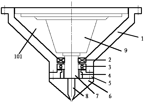
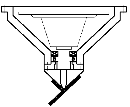
[0022] Example 1 combined figure 1 and figure 2 Describe this embodiment, complete the welding of 5mmTA5 titanium alloy T-shaped fillet weld, a kind of T-shaped reinforced structure friction stir welding device, comprise the power mechanism 9 that is used for driving device to weld, and power mechanism 9 adopts existing friction stir welding The equipment is sufficient, and also includes a structural shaft sleeve 1, one end of which is fixed on the power mechanism 9 through a fixing bolt, and the other end of the structural shaft sleeve 1 is provided with a stirring needle sleeve 7, and the stirring needle sleeve 7 is rotatably supported on the structural bushing 1 through the deep groove ball bearing 3, one end of the stirring needle bushing 7 is installed on the output shaft of the power mechanism 9, and the other end of the stirring needle bushing 7 is installed with a stirring needle 8, stirring The needle 8 is fixed on the stirring needle bushing 7 by fixing bolts, the ...

Embodiment 2

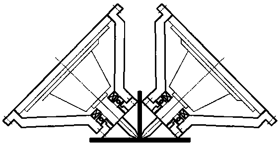
[0031] combine figure 1 and image 3 This embodiment is described. A T-shaped reinforced structure friction stir welding device and method in this embodiment adopts two pieces of equipment to weld simultaneously on both sides. It is set in this way to reduce welding deformation, improve welding efficiency, and reduce labor intensity of welding workers. Other requirements are the same as in Example 1.

Embodiment 3

[0033] combine figure 1 and image 3 Describe this embodiment, a T-shaped reinforced structure friction stir welding device and method according to this embodiment, the apex angles of the static shoulders are 120° and 60° respectively. Such setting can realize the welding of T-shaped structures with different angles on both sides. Other requirements are the same as in Example 1.


PUM

PropertyMeasurementUnit
Top angleaaaaaaaaaa

Abstract

The invention discloses a stirring friction welding device for a T-shaped reinforcement structure and a welding method thereof. The welding device comprises a power mechanism and a structure shaft sleeve, wherein the structure shaft sleeve is installed on the power mechanism; a stirring needle shaft sleeve penetrates through the structure shaft sleeve; the stirring needle shaft sleeve is rotatablysupported on the structure shaft sleeve through a bearing; the stirring needle shaft sleeve is installed on an output shaft of the power mechanism; a stirring needle is installed on the stirring needle shaft sleeve; an angular welding seam static shaft shoulder is arranged outside the stirring needle in a sleeving mode; the angular welding seam static shaft shoulder is arranged on a top sleeve; asealing ring is arranged between the stirring needle shaft sleeve and the structure shaft sleeve; and two ends of the structure shaft sleeve are sealed by the power mechanism and the sealing ring toform a cooling oil cavity. According to the welding device, the complexity of a main shaft structure of a machine tool is greatly reduced, and the application range of the stirring friction welding device is widened. Due to the split design and effective cooling of the stirring needle and the static shaft shoulder structure, the modularization of the static shaft shoulder and the stirring tool isachieved, the clamping is convenient, and the service life of the welding device is greatly prolonged.

Description

technical field [0001] The invention relates to the field of friction stir welding, in particular to a T-shaped reinforced structure friction stir welding device and a welding method thereof. Background technique [0002] There are a large number of T-shaped structures in ships, airplanes, rail transit panels, etc. In order to ensure the rigidity and stability of the structure, strict requirements are put forward for the dimensional accuracy of welding T-shaped profiles and the welding of T-shaped profiles and panel panels. When the disturbance is strict, it is necessary to control Within 5mm per meter. If the arc fusion welding method is used for welding, due to the large heat input and large post-weld deformation, it is difficult to control the welding deformation. Structural security. Friction stir welding is used for solid phase welding, which can realize low stress, small deformation and high precision welding. Friction stir welding mainly produces a large amount of f...

Claims


Application Information

Patent Timeline
IPC IPC(8): B23K20/12B23K20/26
CPCB23K20/125B23K20/26
Inventor 高福洋郭宇凡邱胜闻郁炎
Owner 725TH RES INST OF CHINA SHIPBUILDING INDAL CORP
Why Eureka
Try Eureka