Full face respiratory mask with integrated nasal interface

a full-face mask and nasal interface technology, applied in the field of full-face masks, can solve the problems of less comfortable and intrusive, less comfortable for users, heavy and bulky, etc., and achieve the effect of reducing the variation among the surfaces, and reducing the complexity of sealing

Active Publication Date: 2007-06-07
PHILIPS RS NORTH AMERICA LLC
View PDF14 Cites 290 Cited by
  • Summary
  • Abstract
  • Description
  • Claims
  • Application Information

AI Technical Summary

Benefits of technology

[0011] Accordingly, it is an object of the present invention to provide a patient interface that overcomes the shortcomings of conventional oral-nasal masks. This object is achieved according to one embodiment of the present invention by providing a patient interface that includes a faceplate and a seal member coupled to the faceplate. The seal member contacts the user's face to provide a sealed interface with the user. The seal member includes an oral cushion portion and a nasal interface portion. The oral cushion portion provides a sealed interface with the user over a sealing area that at least partially surrounds the user's mouth. The nasal interface portion is integral with the oral cushion portion and contacts at least a portion of the user's nose below the bridge of the nose. The nasal interface portion provides a sealed interface with a surface of such a user proximate to the nares of such a user. The patient interface having this configuration provides a contacting area on the user's face that is less than conventional oral-nasal masks and also reduces the complexity of sealing, because both the sealing surface and the variation among the surfaces is reduced.

Problems solved by technology

Commonly, in prior mask configurations, a good mask-to-face seal has been attained in many instances only with considerable discomfort to the user.
This problem is most crucial because such masks are typically worn for an extended period of time.
Due to their size and bulk, they may be less comfortable and more intrusive than other masks.
Oral-nasal mask are typically heavy and bulky, may interfere with a user's facial comfort, and may not facilitate the wearing of eyeglasses.
Some oral-nasal masks may irritate a user's nose bridge, which typically is an area of thin skin, where even slight pressure can cause a blood flow constriction, and, hence, skin breakdown and / or discomfort.
It can be difficult to achieve a good seal in typical oral-nasal masks due to the large and varied area being covered.
Another disadvantage of conventional masks is the forehead support.
The forehead support, however, is often the source of pressure point and skin break down.

Method used


Image

  • Full face respiratory mask with integrated nasal interface
  • Full face respiratory mask with integrated nasal interface
  • Full face respiratory mask with integrated nasal interface

Examples


first embodiment

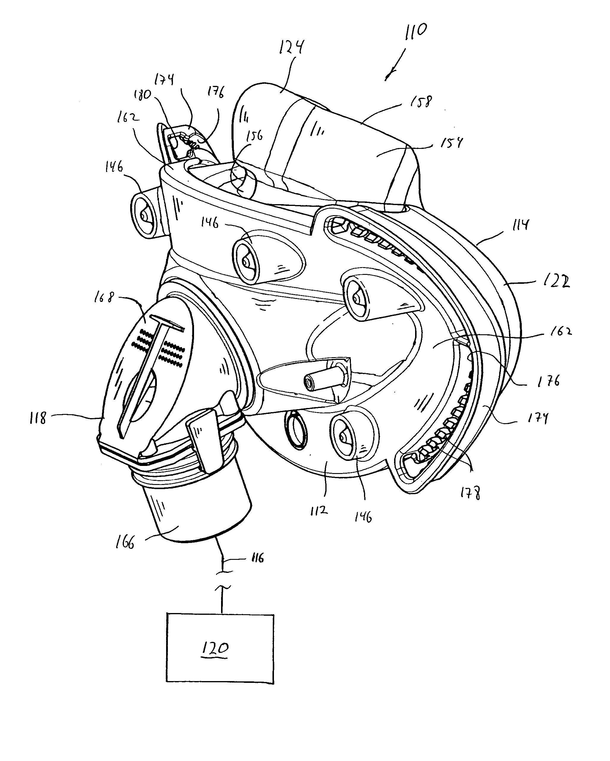
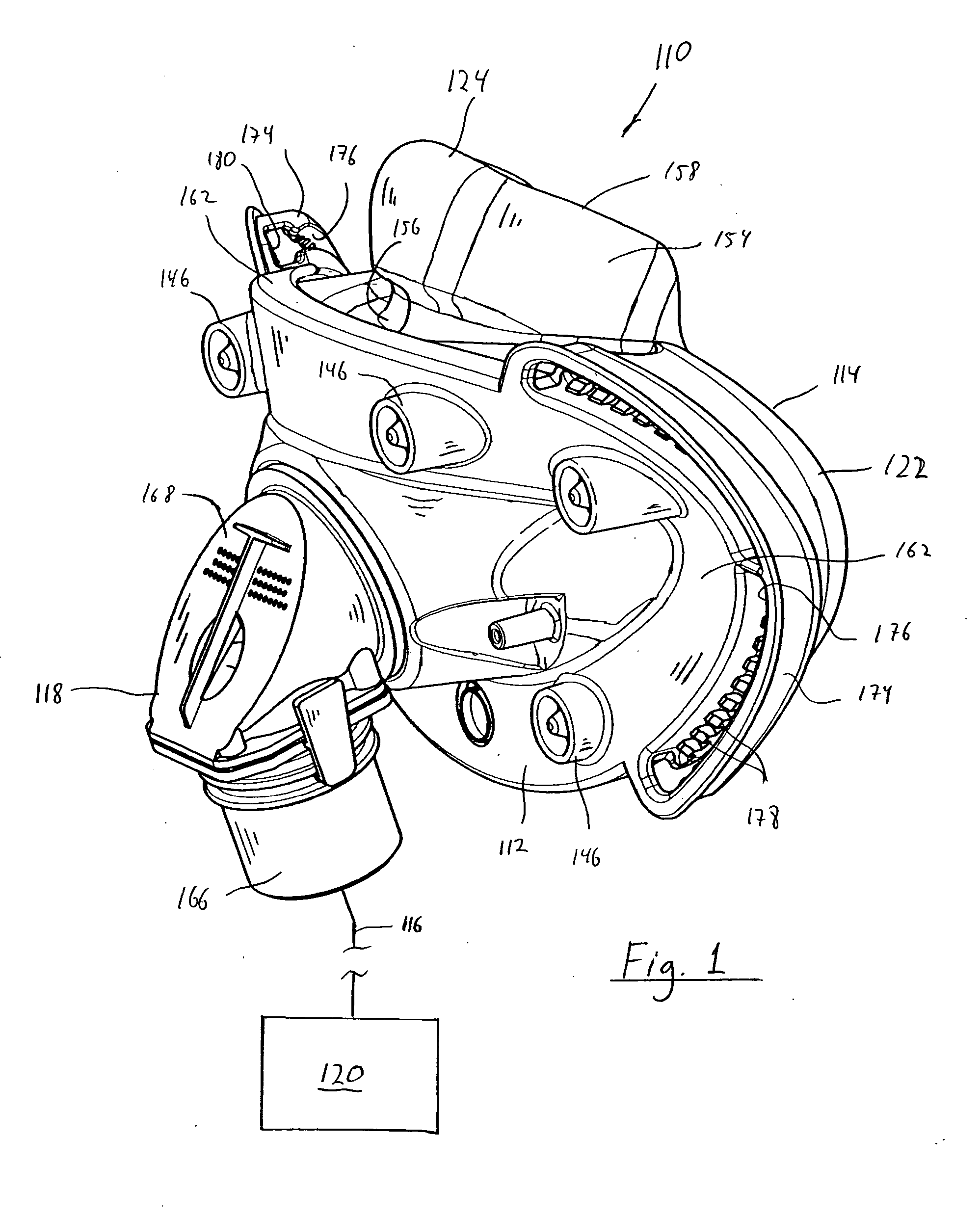
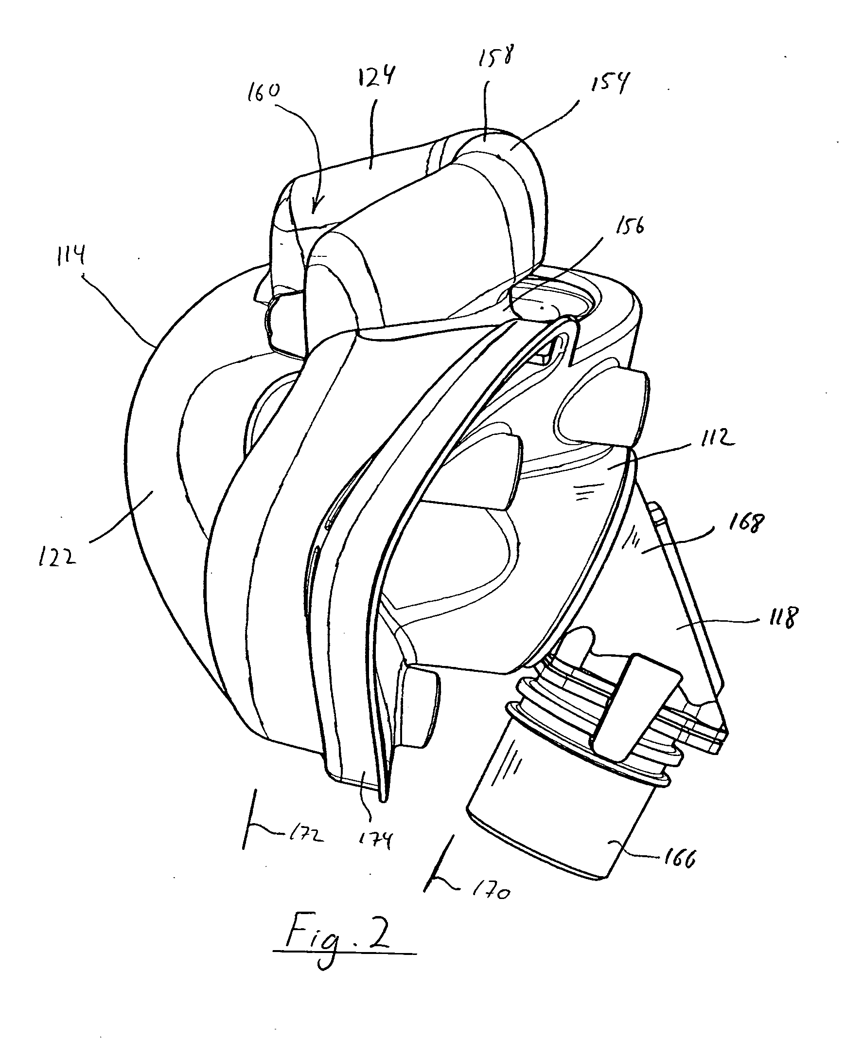
[0062] The present invention contemplates that the faceplate and the seal member, including the oral cushion portion and the nasal interface portion, can have a variety of configurations. Many of these possible alternative configurations are illustrated in the attached figures and described below. A first embodiment for the faceplate and seal member according to the principles of the present invention shown in FIGS. 1-5 will now be described.

[0063] As can perhaps best be seen in FIGS. 4-5, oral cushion portion 122 is a gas-filled cushion having a U-shaped cross section. An exemplary embodiment of a gas-filled cushion suitable for use in the present invention is disclosed in co-pending provisional U.S. patent application Ser. No. 11 / 599,133, (“the '133 application”) the contents of which are incorporated herein by reference.

[0064] Oral cushion portion includes a curved portion 126, an inner side wall 128, an outer side wall 30, and an interior 132. Oral cushion portion 122 is prefer...

eighth embodiment

[0091]FIG. 27 illustrates patient interface assembly 900 that includes a headgear 902 and a patient interface 904. Patient interface 904 corresponds to patient interface 110 except that the nasal interface portion includes a pair of nasal pillows rather than a cup-shaped cushion. Headgear 902 includes a pair of straps 906 and 908 that extend around the back of the user's head and are joined together at strip portion 909. A coupling member 910 is coupled to strip portion 909 such that the coupling member is selectively moveable along the strip portion as indicated by arrow A. The position of coupling member 910 on strip portion 909 can be controlled by a locking mechanism (not shown) or it can be left uncontrolled, so that the coupling member seeks the optimum position on the strip portion for each user. A connecting strap 912 connects coupling member 910 to a headgear clip 914.

[0092] Headgear clip 914 corresponds to the headgear clip shown in the '133 application and includes a port...

ninth embodiment

[0093]FIG. 28 illustrates a patient interface assembly 940 that includes a headgear 942 and a patient interface 944. Patient interface 944 corresponds to patient interface 310. In this embodiment, headgear straps 946 are coupled to the faceplate of the patient interface using a hook clip 340, as discussed above with respect to the embodiment illustrated in FIGS. 8-14. Hook clip 340 can be located in any pair of openings 360 to suit the particular needs / desires of the user. In addition to straps that wrap around the back of the head, headgear 942 includes a strap 948 that wraps over the top of the head. An optional chin strap is shown by dashed lines 950. The present invention also contemplates providing a cap in addition to, or in place of the headgear straps. An example of such a cap is disclosed in U.S. Pat. No. 6,805,117.


PUM


Abstract

A patient interface that reliably and comfortably seals a user's face by providing an oral-nasal mask that includes an integrated nasal interface. The patient interface includes a seal member having an oral cushion portion configured to surround the user's mouth and a nasal interface portion that provides an interface with the user's nose. The seal member, including the oral cushion portion and the nasal interface portion, is a unitary member. Finally, the nasal interface portion remains below the bridge of the nose.

Description

CROSS-REFERENCE TO RELATED APPLICATIONS [0001] This application claims priority under 35 U.S.C. § 119(e) from provisional U.S. patent application No. 60 / 748,311, filed Dec. 7, 2005, the contents of which are incorporated herein by reference.BACKGROUND OF THE INVENTION [0002] 1. Field of the Invention [0003] The present invention relates, in general, to a full face mask that provides a sealed interface with the nose and mouth of a user, and, in particular, to a full face mask having an oral cushion portion that seals generally around the mouth and a nasal interface portion that seals generally at or around the nares and remains below the bridge of the nose. [0004] 2. Description of the Related Art [0005] A variety of respiratory masks are known that have flexible seals, cover a portion of a user's face, and are designed to create a seal against the user's face. Because of the sealing effect that is created, gases can be provided at a positive pressure within the mask for consumption ...

Claims


Application Information

Patent Timeline
Patent Type & Authority Applications(United States)
IPC IPC(8): A62B18/02A62B18/08
CPCA61M16/06A61M16/0666A61M16/0683A61M16/0611A61M16/0605
Inventor HO, PETER CHI FAIEATON, JASON P.
Owner PHILIPS RS NORTH AMERICA LLC
Why Eureka
Try Eureka