Connecting structure and elbow assembly

A connection structure and elbow technology, which is applied to the details of milling machine equipment, metal processing equipment, milling machine equipment, etc., can solve the problem that the orientation of the elbow cannot be adjusted, and achieve the effect of a large working range

Pending Publication Date: 2019-08-23
ZHUHAI GREE INTELLIGENT EQUIP CO LTD +1
View PDF0 Cites 1 Cited by
  • Summary
  • Abstract
  • Description
  • Claims
  • Application Information

AI Technical Summary

Problems solved by technology

[0003] The main purpose of the present invention is to provide a connection structure and an elbow assembly to solve the problem that the direction of the elbow cannot be adjusted in the prior art

Method used


Image

  • Connecting structure and elbow assembly
  • Connecting structure and elbow assembly
  • Connecting structure and elbow assembly

Examples


Embodiment Construction

[0025] It should be noted that, in the case of no conflict, the embodiments in the present application and the features in the embodiments can be combined with each other. The present invention will be described in detail below with reference to the accompanying drawings and examples.

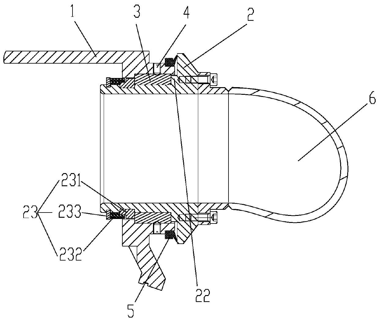
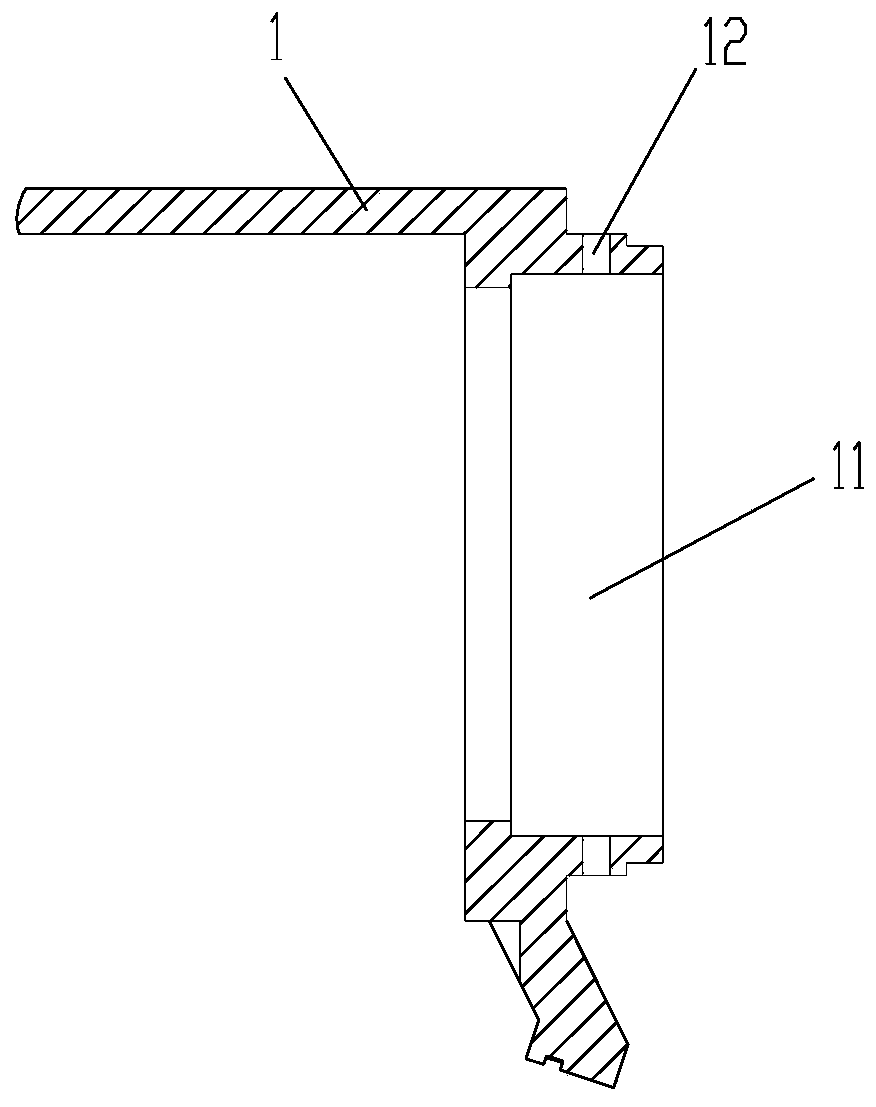
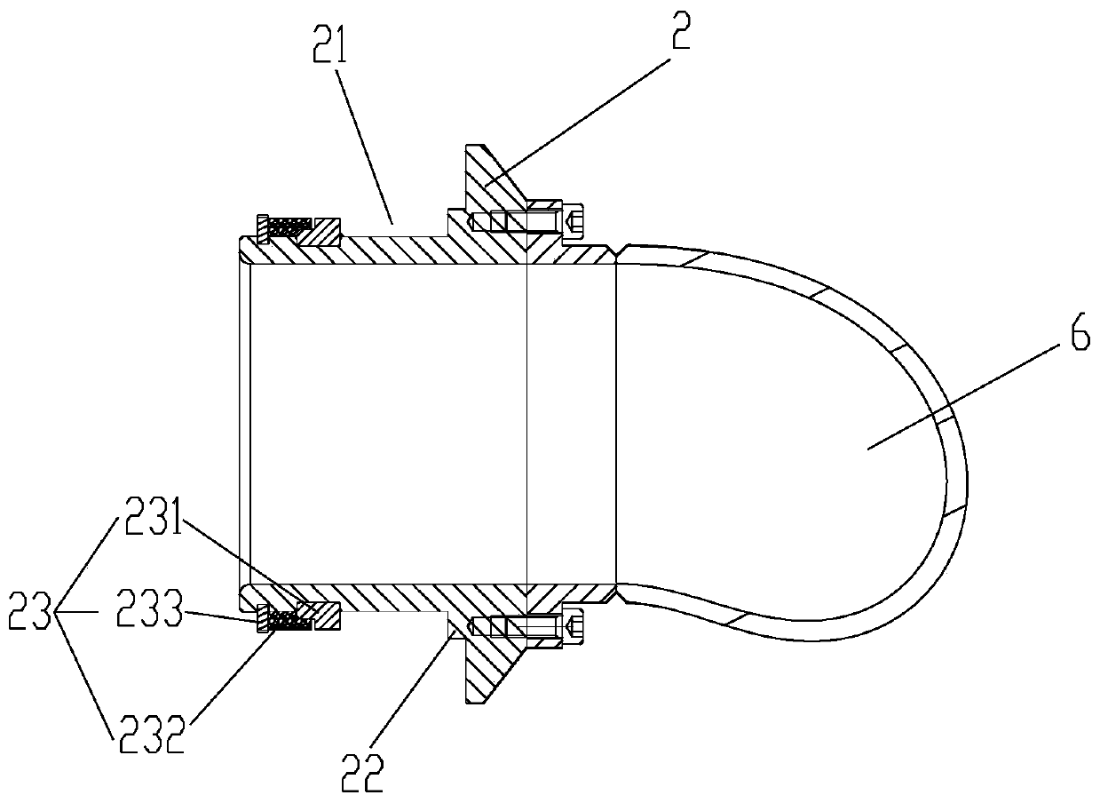
[0026] Please refer to Figure 1 to Figure 5 , the present invention provides a connection structure, including: a first part 1; a second part 2, the second part 2 is provided with a first annular groove 21; a sleeve 3, at least part of the sleeve 3 around a predetermined axis of rotation It is rotatably sleeved on the second part 2 and located in the first annular groove 21, so that the movement of the sleeve 3 along the predetermined axis of rotation is limited by the first annular groove 21; wherein, the first part 1 and the sleeve 3 is fixedly connected so that the first part 1 is rotatably arranged with the sleeve 3 relative to the second part 2.

[0027] The connection structure of the ...


PUM


Abstract

The invention provides a connecting structure and an elbow assembly. The connecting structure comprises a first part, a second part and a sleeve, wherein the second part is provided with a first annular groove, at least a part of the sleeve is rotatably arranged on the second part in a sleeving mode around a preset rotation axis and is positioned in the first annular groove, the first annular groove limits movement of the sleeve in the preset rotation axis direction, the first part is fixedly connected with the sleeve, so that the first part can be rotationally arranged along with the sleeve relative to the second part. The connecting structure solves the problem that in the prior art, orientation of an elbow cannot be adjusted.

Description

technical field [0001] The invention relates to the technical field of connectors, in particular to a connection structure and an elbow assembly. Background technique [0002] At present, most of the elbows used for milling head routing adopt a fixed installation method. After the angle of the elbow is selected, the elbow is fixed with fasteners. This installation method cannot adjust the orientation of the routing elbow, which will cause the milling head to The rotation angle is limited. Contents of the invention [0003] The main purpose of the present invention is to provide a connection structure and an elbow assembly to solve the problem in the prior art that the orientation of the elbow cannot be adjusted. [0004] In order to achieve the above object, according to one aspect of the present invention, a connection structure is provided, including: a first part; a second part, a first annular groove is provided on the second part; a sleeve, at least part of which wra...

Claims


Application Information

Patent Timeline
Patent Type & Authority Applications(China)
IPC IPC(8): B23C9/00
CPCB23C9/00
Inventor 王永兴
Owner ZHUHAI GREE INTELLIGENT EQUIP CO LTD
Why Eureka
Try Eureka