Industrial robot

a robot and industrial technology, applied in the direction of arms, manufacturing tools, gears, etc., can solve the problems of limited action speed, poor reliability of gantry manipulators, and need of expensive and energy-consuming actuators (motors), and achieve the effect of high precision and easy manufacturing

Inactive Publication Date: 2005-12-13
ABB (SCHWEIZ) AG
View PDF9 Cites 35 Cited by
  • Summary
  • Abstract
  • Description
  • Claims
  • Application Information

AI Technical Summary

Benefits of technology

[0030]The inventive concept comprises connecting at least one of the movable units to the manipulated platform via only one of the six articulated rods. In this way, no requirements are made for orientation in any direction of the arm on which the link in question is mounted via a joint. This provides many possibilities of introducing pivotable lower arms to increase the working range of the manipulator in the z-direction. This is of particular importance when a manipulator with only three degrees of freedom (x, y, z) is to be designed.
[0031]To obtain a large working range in the xy-plane, that is, in the plane in which at least two of the liner paths are mounted, according to an advantageous embodiment of the invention two of the linear paths with associated movable units are mounted such that at least four of the six links are able to move freely between the two linear paths. This makes it possible for the linkage to perform large movements in the y-direction while simultaneously performing large movements in the z-direction, since the arm system in the middle of the working range between the linear paths will have its greatest mobility in all directions. This configuration of the linear paths is the optimal one also from the point of view of rigidity of the manipulator if the linear paths are mounted such that the normal vectors to the mounting surfaces of the movable units for one of the linear paths are parallel but directed opposite to the mounting surfaces of the movable units for the other linear path.
[0033]The inventive concept also comprises different designs for obtaining an extended working range of the manipulated platform with the aid of lever arms. These designs are based on relative movements between two or more movable units, with the aid of articulated couplings between the movable units, giving rise to oscillations of arms mounted on the movable units. In this way, the linear movements of the movable units will give rise to large circular movements of those joints which connect articulated rods to the oscillating arms, and large movements of the manipulated platform are obtained.
[0034]In an advantageous embodiment of the invention, at least four of the joints between the manipulated platform and the six articulated rods are mounted along a common symmetrical line, which corresponds to the previously mentioned mathematical lines coinciding. If, in addition, a fifth joint for manipulating the platform in the z-direction is mounted on this symmetry line, the platform will be constituted by a rod or a shaft, which may then be rotated around by the sixth articulated rod via a lever arm or via a universal transmission. This gives a very compact platform, which is easy to manufacture with high precision. In addition, this platform provides a possibility of simply using ordinary ball or roller bearings to implement the joints in question.

Problems solved by technology

The series connection of the linear paths with their associated movable units and actuators impose a number of restrictions on current gantry manipulators.The manipulator becomes very heavy, which limits its speed of action and results in a need of expensive and energy-consuming actuators (motors).The manipulator becomes weak and when objects or tools are moved, a undesired oscillation of the manipulator is obtained in case of movement along the path where the movement is to be made, and especially when the movement is to be stopped, so-called overshoots are obtained.The manipulator becomes resilient when the platform is to generate forces between tools and objects, unless very expensive and complex solutions for the liner paths are used.For the movable actuators with their associated measuring sensors, movable cabling is required, which causes poor reliability in gantry manipulators.It is difficult to obtain high accuracy of the manipulator without providing expensive solutions involving, for example, air bearings, which at the same time give the manipulator limited speed of action.Two parallel linear paths are normally used for supporting the second linear path in the serial kinematic chain.
This gives rise to an effect similar to that of a drawer in a chest of drawers getting wedged when being pushed it, and requires special, costly solutions to manage.
However, this manipulator has too small a working range to replace the gantry manipulators that are used at present in various industrial applications.
In addition, this parallel kinematic robot requires six actuators also when only four degrees of freedom are to be manipulated, which results in an unnecessarily high price of the manipulator.
Finally, the control programs which are to attend to the movement of the manipulator become extensive.

Method used


Image

  • Industrial robot
  • Industrial robot
  • Industrial robot

Examples


Embodiment Construction

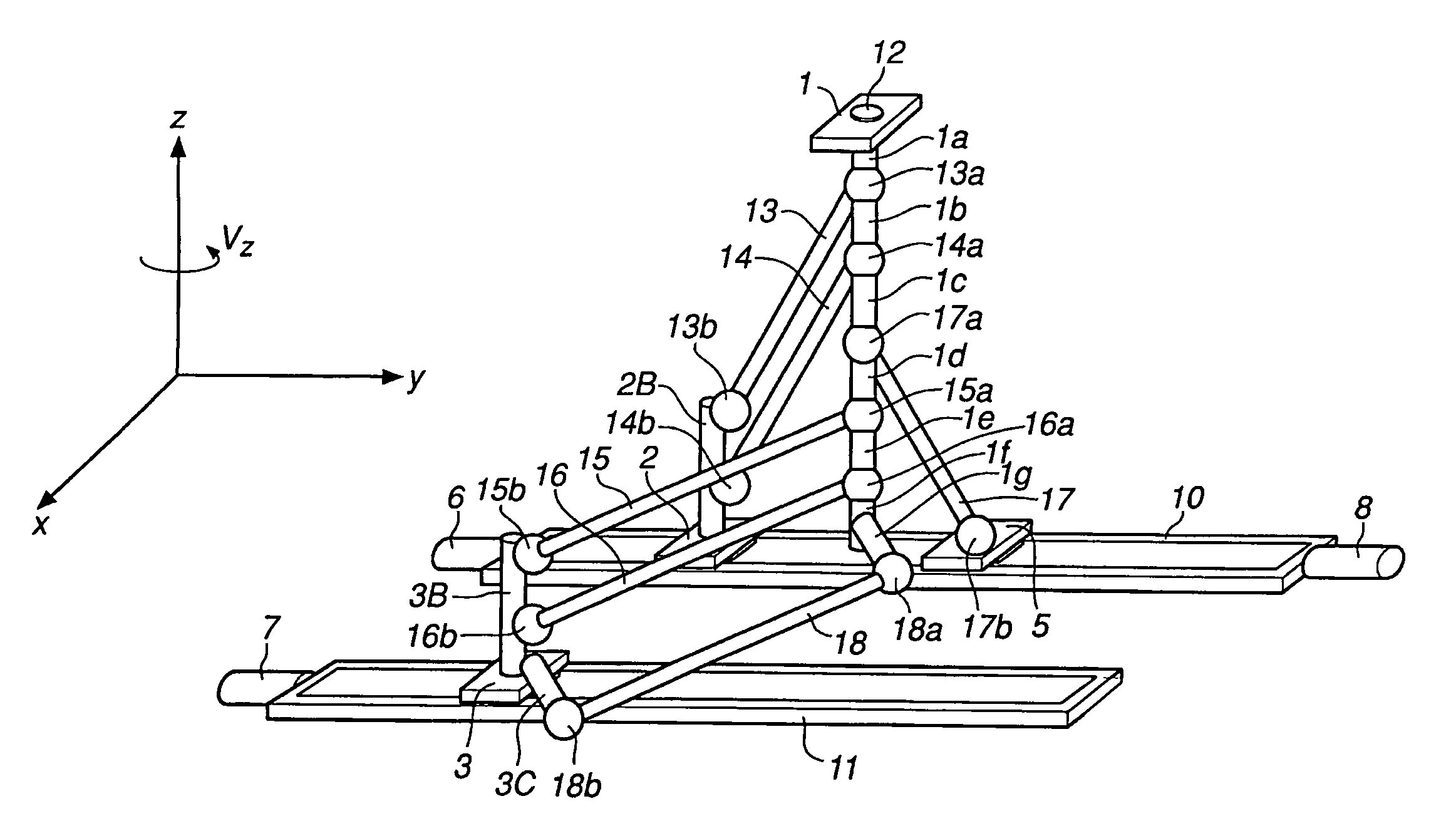
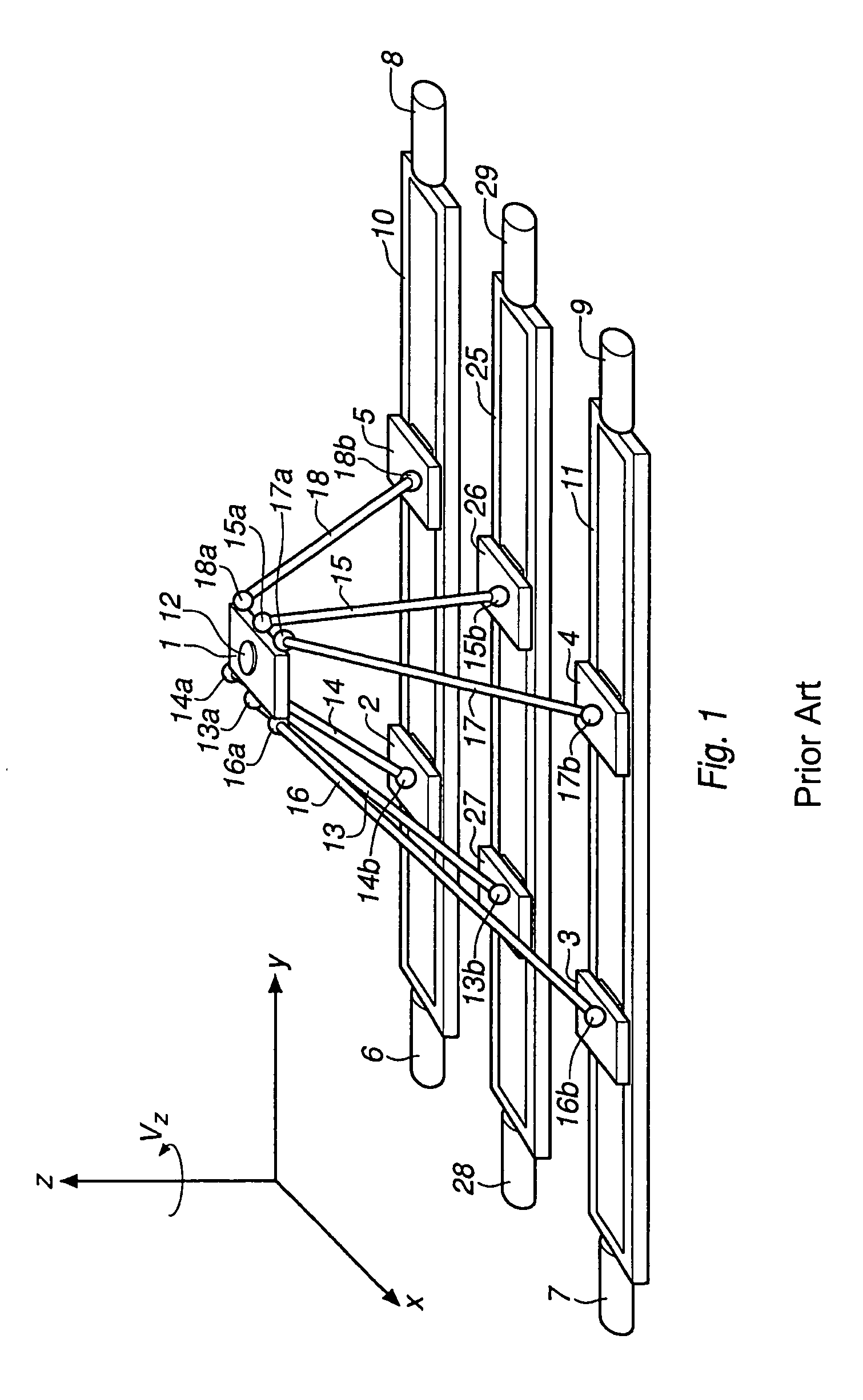
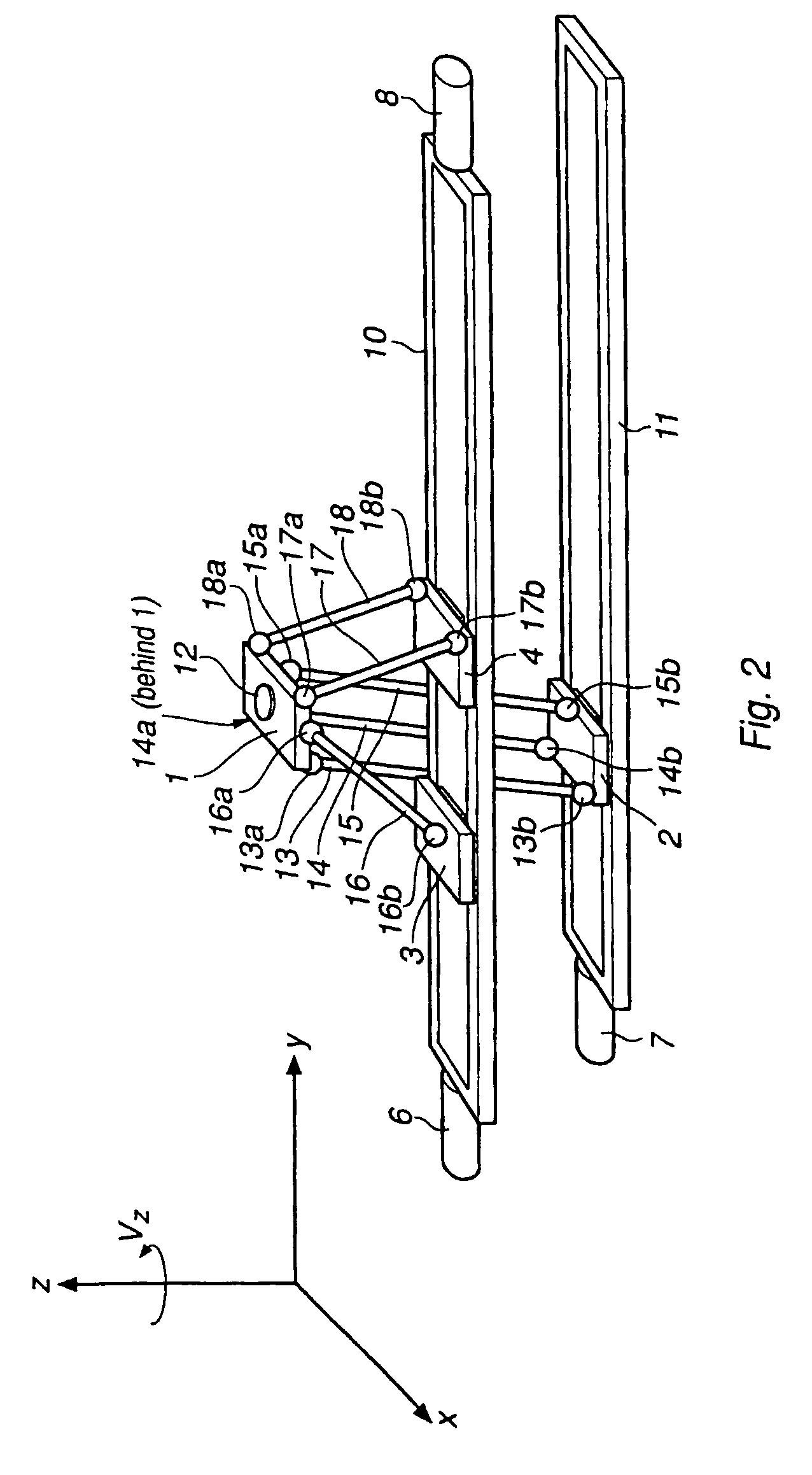
[0054]FIG. 1 shows the prior art for manipulating, on linear paths 10, 11 and 25, a platform 1 by means of links 13–18, which only transmit compressive and tensile stresses. The six links 13–18 are provided at each end with joints 13a–18a and 13b–16b, respectively. The joints have two or three degrees of freedom and the links are mounted, via the joints 13a–18a, on the platform 1 that is to be manipulated. With the joints 13b–18b, the links are mounted on the movable units 2, 3, 4, 5, 26, 27 with one link for each movable unit. The movable units are controlled by actuators 6, 7, 8, 9, 29 and 28 and may be positioned along the linear paths 10, 11, 25 independently of each other. By performing this positioning in a certain pattern given by the kinematics of the manipulator, the platform may be caused to move in the x-, y-and z-directions and to obtain rotations around the z-axis(Vz). It is also possible to obtain rotations around the x-and y-axes, but there is no need for that in most...


PUM


Abstract

An industrial robot for movement of an object in space comprising a platform arranged for carrying the object, a first arm arranged for influencing the platform in a first movement and comprising a first actuator and two links, each of which comprises an outer joint arranged in the platform and an inner joint arranged in the first actuator, a second arm arranged for influencing the platform in a second movement and comprising a second actuator and two links, each of which comprises an outer joint arranged in the platform and an inner joint arranged in the second actuator, and a third arm arranged for influencing the platform in a third movement and comprising a third actuator and a link, which comprises an outer joint arranged in the platform and an inner joint arranged in the third actuator. The first actuator comprises a first motor, a first path arranged in a first plane and a first carriage linearly movable along the first path, whereby the two inner joints are displaceable in parallel, the second actuator comprises a second motor, a second path arranged in a second plane and a second carriage linearly movable along the second path, whereby the two inner joints are displaceable in parallel, and the third actuator comprises a third motor, a third path arranged in a third plane and a third carriage linearly movable along the third path, whereby the inner joint is linearly displaceable.

Description

TECHNICAL FIELD[0001]The present invention relates to an industrial robot comprising a manipulator and control equipment for moving an object in space. The manipulator comprises a platform jointly supported by a plurality of arms comprising linkages. Each arm is associated with an actuator with the purpose of moving the linkage of the arm in parallel such that a movement of the platform is attained. The task of the platform is to directly or indirectly support tools or objects, large as well as small, for movement, measurement, processing, working, joining, etc. In particular, the manipulator is intended to be used in the manufacturing industry but also transfer of goods and passageways for passengers in harbours and airports may come into question.BACKGROUND ART[0002]A manipulator which comprises more than one arm and where at least two arms each form a chain of joints between the actuators of the manipulator and the platform which is to be manipulated is called a parallel kinemati...

Claims


Application Information

Patent Timeline
Patent Type & Authority Patents(United States)
IPC IPC(8): B23Q1/54B25J9/04B25J11/00B25J17/00B25J17/02F16H21/46
CPCB23Q1/5462B25J17/0266B25J9/0072B25J9/0036B25J9/0042Y10T74/20335Y10T74/20341
Inventor BROG.ANG.RDH, TORGNY
Owner ABB (SCHWEIZ) AG
Why Eureka
Try Eureka