
a clamp

A wire clip and slot technology, applied in the field of wire clips, can solve the problem that the wire clip cannot hold sheet metal parts of different thicknesses, etc.

Active Publication Date: 2020-12-01
ANHUI JIANGHUAI AUTOMOBILE GRP CORP LTD
View PDF7 Cites 0 Cited by
  • Summary
  • Abstract
  • Description
  • Claims
  • Application Information

AI Technical Summary

Problems solved by technology

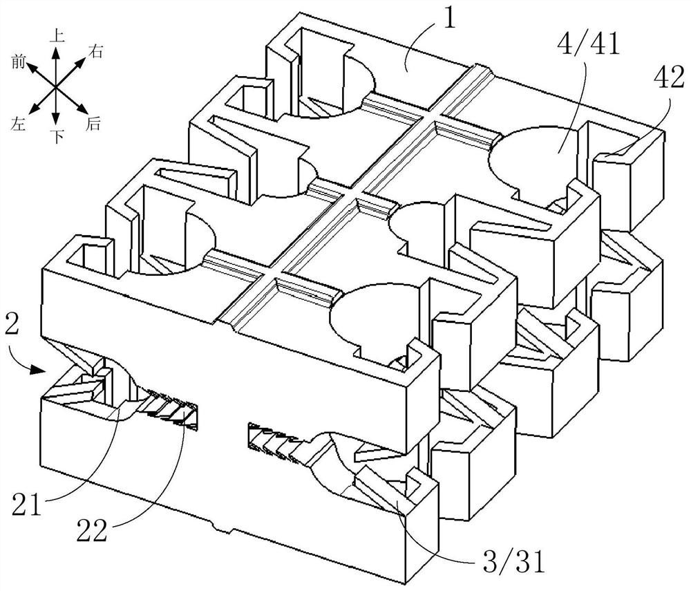
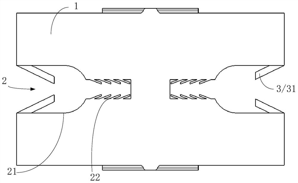
[0003] In order to solve the above technical problems, the main purpose of the present invention is to provide a wire clip, which aims to solve the problem that the existing wire clip cannot be clipped on sheet metal parts of different thicknesses

Method used


Image

  • a clamp
  • a clamp
  • a clamp

Examples


Embodiment Construction

[0030] The following will clearly and completely describe the technical solutions in the embodiments of the present invention with reference to the accompanying drawings in the embodiments of the present invention. Obviously, the described embodiments are only part of the embodiments of the present invention, not all of them. Based on the embodiments of the present invention, all other embodiments obtained by persons of ordinary skill in the art without creative efforts fall within the protection scope of the present invention.

[0031] It should be noted that if there are directional indications involved in the embodiment of the present invention, the directional indications are only used to explain the relative positional relationship, movement conditions, etc. between the components in a specific posture. If the specific posture changes , then the directional indication changes accordingly.

[0032] In addition, if there are descriptions involving "first", "second" and so o...


PUM


Abstract

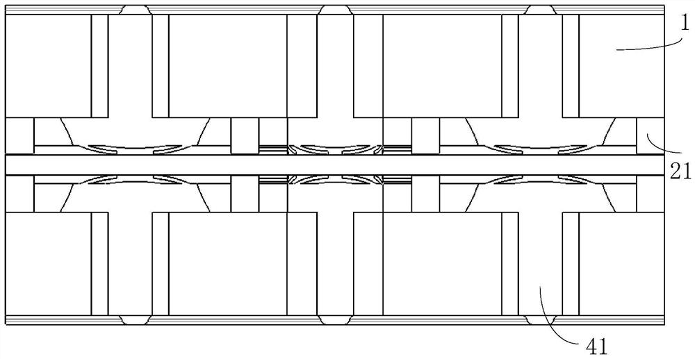
The invention discloses a wire clamp which is used for fixing a wire harness. The wire clamp comprises a body. A first clamping groove is formed in the outer surface of the body. The first clamping groove comprises a first groove section and a second groove section which are distributed in the groove depth direction. The first groove section is arranged close to the groove notch of the first clamping groove. The body comprises a first groove section and a second groove section. The groove width of the first groove section is larger than that of the second groove section. Limiting structures are arranged on the inner side walls, close to the groove notches, of the first groove section and the second groove section. The limiting structures are used for limiting a clamped object to be separated from the first clamping groove at the groove notch. The body is further provided with a fixing structure used for fixing the wire harness. According to the wire clamp, the first groove is formed inthe body, so that the wire clamp can be clamped on sheet metal parts with different thicknesses. The fixation of the wire clamp is facilitated, and the application range of the wire clamp is widened.

Description

technical field [0001] The invention relates to the technical field of automobiles, in particular to a wire clip. Background technique [0002] In modern automobiles, there are usually various clamps for fixing the pipelines. The main function is to fix the pipelines on the car sheet metal or the frame, effectively preventing the interference and wear of the pipelines when they are too fast. The number of pipelines fixed by the clamps in the prior art is limited, there is no unified constraint, and the fixation is not beautiful, and the clamps can only be clamped on sheet metal with a fixed thickness, so the use has certain limitations. Contents of the invention [0003] In order to solve the above-mentioned technical problems, the main purpose of the present invention is to provide a wire clamp, aiming at solving the problem that the existing wire clamp cannot be clamped on sheet metal parts with different thicknesses. [0004] In order to achieve the above object, the p...

Claims


Application Information

Patent Timeline
Patent Type & Authority Patents(China)
IPC IPC(8): H02G3/02
CPCH02G3/02
Inventor 朱路生李昕王世强杨菲菲崔建维吴立慧
Owner ANHUI JIANGHUAI AUTOMOBILE GRP CORP LTD
Learn More