Wire rod circuit and wire rod

A circuit and wire technology, applied in the field of charging, can solve problems such as poor compatibility

Pending Publication Date: 2019-08-23
SHENZHEN TIMES INNOVATION TECH CO LTD
View PDF0 Cites 6 Cited by
  • Summary
  • Abstract
  • Description
  • Claims
  • Application Information

AI Technical Summary

Problems solved by technology

[0005] The purpose of the present invention is to provide a wire circuit and wire to alleviate the technical problems that existing charging products only support one fast charging protocol and have poor compatibility

Method used


Image

  • Wire rod circuit and wire rod
  • Wire rod circuit and wire rod
  • Wire rod circuit and wire rod

Examples


Embodiment 1

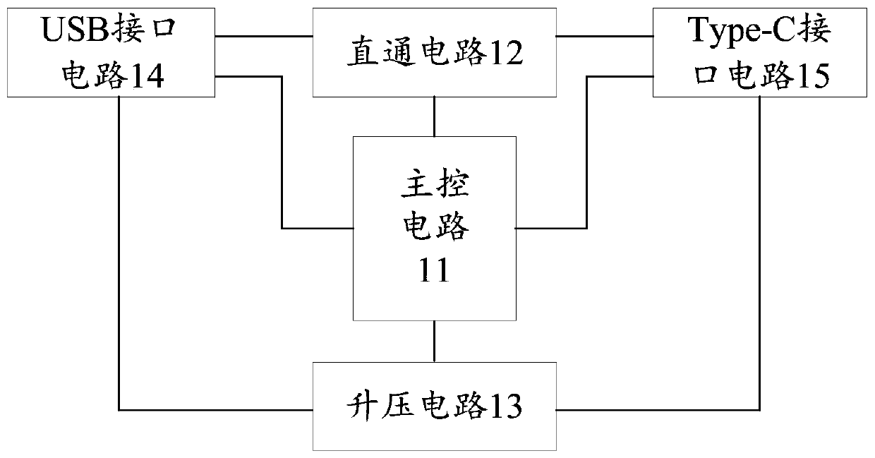
[0039] figure 1 is a schematic structural diagram of a wire circuit according to an embodiment of the present invention, such as figure 1 As shown, the wire circuit includes: a main control circuit 11, a direct circuit 12, a boost circuit 13, a USB interface circuit 14 and a Type-C interface circuit 15; , Type-C interface circuit 15, USB interface circuit 14 are connected, direct circuit 12 is connected with Type-C interface circuit 15, USB interface circuit 14 respectively, booster circuit 13 is connected with Type-C interface circuit 15, USB interface circuit 14 respectively ;

[0040] Type-C interface circuit 15, for connecting target equipment;

[0041] USB interface circuit 14, used for connecting power transmission equipment;

[0042] The main control circuit 11 is used to obtain the charging protocol of the target device and the fast charging protocol of the power transmission device after the Type-C interface circuit 15 is connected to the target device, and the USB...

Embodiment 2

[0078] The embodiment of the present invention also provides a wire, which includes the wire circuit in the first embodiment above, and further includes: a charging wire; the wire circuit is built into the charging wire.


PUM


Abstract

The invention provides a wire rod circuit and a wire rod. A Type-C interface circuit in the wire rod circuit is connected with target equipment, and a USB interface circuit is connected with power transmission equipment; a master control circuit at the Type-C interface circuit is connected with the target equipment; and after the USB interface circuit is connected with the power transmission equipment, a charging protocol of the target equipment and a fast charging protocol of the power transmission equipment are obtained, and a target charging circuit is determined in a direct-through circuitand a booster circuit based on the charging protocol and the fast charging protocol, so that the fast charging of the target equipment is realized through the target charging circuit. In the wire rodcircuit, no matter whether the charging protocol of the target equipment is matched with the fast charging protocol of the power transmission equipment or not, the fast charging of the target equipment can be realized through the target charging circuit, and the wire rod circuit is compatible with various charging protocols, so the use is convenient, the defect that people carry many chargers when going out is avoided, and the technical problem that an existing charging product only supports one charging protocol and is poor in compatibility is solved.

Description

technical field [0001] The invention relates to the technical field of charging, in particular to a wire circuit and a wire. Background technique [0002] At present, the charging of the electronic product is generally implemented by docking the charger with the electronic product (such as a mobile phone). [0003] However, in such a charging method, an electronic product with a charging protocol can only realize fast charging by relying on a charger supporting the charging protocol. However, due to the different fast charging protocols supported by different electronic products, people need to carry a lot of chargers when traveling, which is inconvenient to use. [0004] To sum up, in the existing charging methods, charging products only support one fast charging protocol, which brings great troubles to consumers. Contents of the invention [0005] The purpose of the present invention is to provide a wire circuit and wire to alleviate the technical problem that existing...

Claims


Application Information

Patent Timeline
Patent Type & Authority Applications(China)
IPC IPC(8): H02J7/00
CPCH02J7/00H02J7/00045
Inventor 罗宜成陈龙扣桂登宇
Owner SHENZHEN TIMES INNOVATION TECH CO LTD
Why Eureka
Try Eureka