Backlight module and liquid crystal module

A technology of backlight module and liquid crystal module, which is applied in optics, nonlinear optics, instruments, etc., can solve the problems of optical diaphragm expansion obstruction, achieve the effects of improving user experience, enhancing display stability, and alleviating expansion obstruction

Pending Publication Date: 2019-08-27
WUHAN CHINA STAR OPTOELECTRONICS TECH CO LTD
View PDF0 Cites 8 Cited by
  • Summary
  • Abstract
  • Description
  • Claims
  • Application Information

AI Technical Summary

Problems solved by technology

[0005] The invention provides a backlight module and a liquid crystal module, so as to alleviate the technical problem that the expansion of the optical film is hindered in the existing backlight module used for narrow frame vehicle display equipment

Method used


Image

  • Backlight module and liquid crystal module
  • Backlight module and liquid crystal module
  • Backlight module and liquid crystal module

Examples


Embodiment Construction

[0040] The following descriptions of the various embodiments refer to the accompanying drawings to illustrate specific embodiments in which the invention may be practiced. The directional terms mentioned in the present invention, such as [top], [bottom], [front], [back], [left], [right], [inside], [outside], [side wall], etc., are only Refer to attached drawings for directions. Therefore, the directional terms used are used to illustrate and understand the present invention, but not to limit the present invention. In the figures, elements with similar structures are denoted by the same reference numerals.

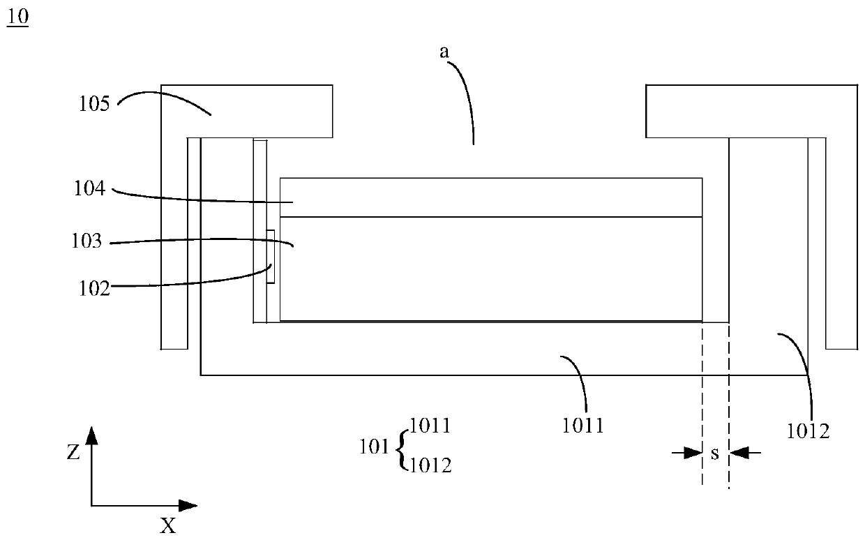
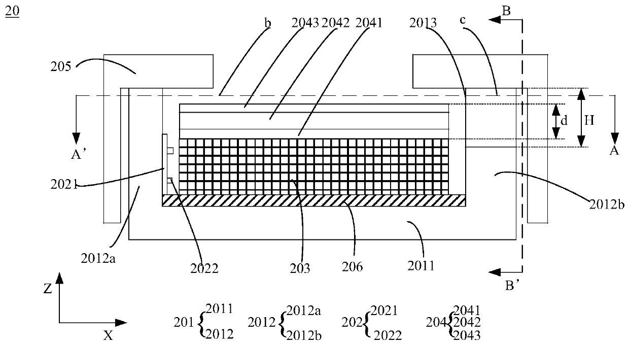
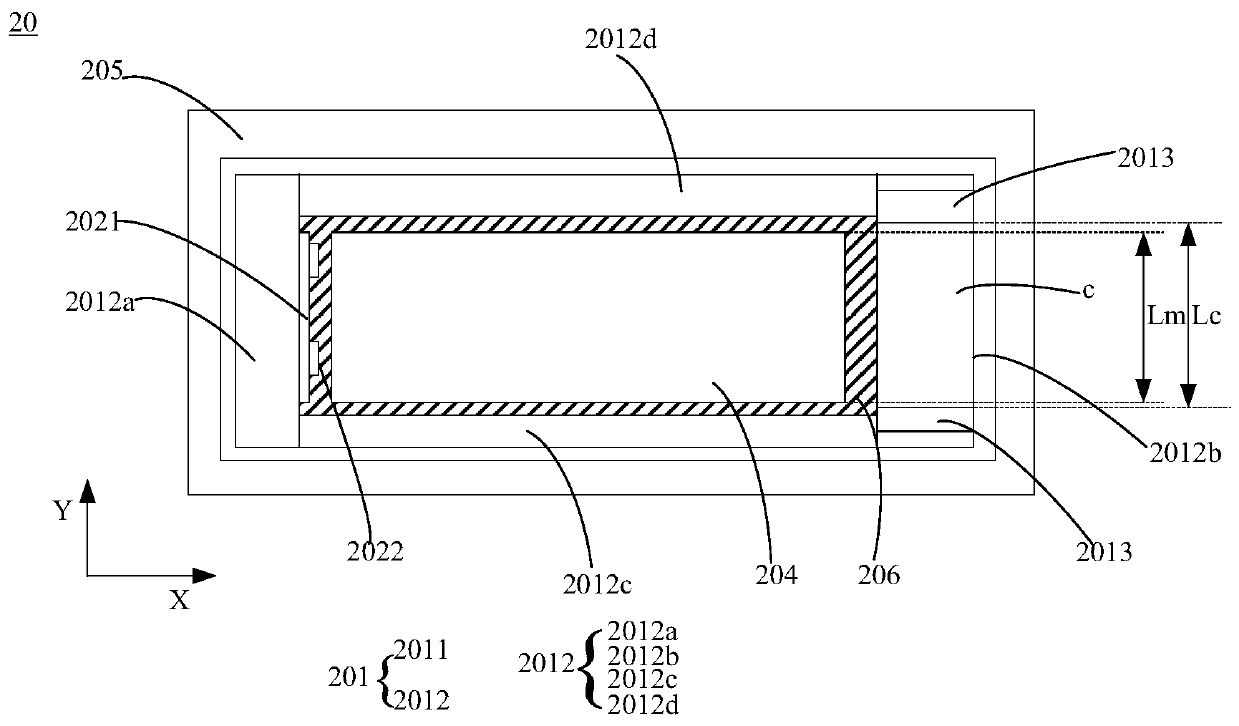
[0041] In the drawings of the present invention, X represents the length direction of the module, Y represents the width direction of the module, and Z represents the height direction of the module.

[0042] The embodiments of the present invention can alleviate the technical problem that the expansion of the optical film is hindered in the existing backlight module used ...


PUM


Abstract

The present invention provides a backlight module and a liquid crystal module. The backlight module comprises a back plate, a light source, a light guiding member, an optical film, and a fixing frame.The back plate comprises a bottom plate and sidewalls; the bottom plate and the sidewalls are formed to a receiving cavity; the light source, the light guiding member, and the optical film are arranged in the receiving cavity; and at least one sidewall is provided with a avoidance notch at a position corresponding to the optical film, and the height of the avoidance notch is greater than or equalto the thickness of the optical film. According to the technical scheme of the present invention, an avoidance notch is arranged at the position corresponding to the optical film on the side, when the optical film is thermally expanded, the deformed optical film is located in the avoidance notch, and there is no wrinkle to the optical film due to the expansion, so that the technical problem thatthe optical film expansion is blocked in the backlight module for the narrow-frame vehicle display device is alleviated, the display stability of the narrow-frame vehicle display device is enhanced, and the user experience is improved.

Description

technical field [0001] The invention relates to the field of display technology, in particular to a backlight module and a liquid crystal module. Background technique [0002] Such as figure 1 As shown, in the backlight module 10 of the existing vehicle-mounted display device, sheet metal parts such as cast aluminum parts are usually used as the backplane 101. The backplane 101 includes a bottom plate 1011 and a side wall 1012, which form a In the housing chamber a, the light source 102, the light guide plate 103, the optical film layer 104, etc. are arranged in the housing chamber a, and the fixing frame 105 is fixed on the back plate 101. In order to realize the narrow frame of the vehicle-mounted display device, the optical film 104, etc. The gap s between 1012 is small. [0003] Under high temperature conditions, the optical diaphragm will expand. Since the optical diaphragm of the vehicle-mounted display device is relatively large overall, the deformation due to expan...

Claims


Application Information

Patent Timeline
Patent Type & Authority Applications(China)
IPC IPC(8): G02F1/13357
CPCG02F1/133608
Inventor 周政
Owner WUHAN CHINA STAR OPTOELECTRONICS TECH CO LTD
Why Eureka
Try Eureka