Backlight module and liquid crystal display module

A technology for backlight modules and light sources, applied in the directions of light guides, optics, optical components, etc., can solve the problems of hindered expansion of optical diaphragms, high power consumption, material limitations, etc., to enhance display stability, improve user experience, and alleviate expansion. hindered effect

Active Publication Date: 2020-11-20
WUHAN CHINA STAR OPTOELECTRONICS TECH CO LTD
View PDF6 Cites 1 Cited by
  • Summary
  • Abstract
  • Description
  • Claims
  • Application Information

AI Technical Summary

Problems solved by technology

At the same time, due to the relatively high power consumption of medium and large-sized vehicle modules, and relatively strict heat dissipation requirements, there are also strict restrictions on the choice of material thickness.
With the increasing demand for ultra-narrow bezels of vehicle-mounted modules in the market, for medium and large-sized vehicle-mounted modules, due to the limitations of module frame size, heat dissipation capacity, and structural strength, conventionally designed modules cannot guarantee the performance of vehicle-mounted displays. The goal of narrow bezel design is achieved under the premise of high reliability requirements of the module
[0004] Therefore, the existing backlight modules and liquid crystal display modules used for narrow frame vehicle display devices, due to the limitation of the frame size, heat dissipation capacity and structural strength of the modules, have the technical problem of hindering the expansion of the optical diaphragm, which needs to be improved.

Method used


Image

  • Backlight module and liquid crystal display module
  • Backlight module and liquid crystal display module
  • Backlight module and liquid crystal display module

Examples


Embodiment Construction

[0026] The technical solutions in the embodiments of the present application will be clearly and completely described below in conjunction with the drawings in the embodiments of the present application. Apparently, the described embodiments are only some of the embodiments of this application, not all of them. Based on the embodiments in this application, all other embodiments obtained by those skilled in the art without making creative efforts belong to the scope of protection of this application.

[0027] In the description of the present application, it should be understood that the terms "center", "longitudinal", "transverse", "length", "width", "thickness", "upper", "lower", "front", " Orientation indicated by rear, left, right, vertical, horizontal, top, bottom, inside, outside, clockwise, counterclockwise, etc. The positional relationship is based on the orientation or positional relationship shown in the drawings, which is only for the convenience of describing the a...


PUM

PropertyMeasurementUnit
thicknessaaaaaaaaaa
thicknessaaaaaaaaaa

Abstract

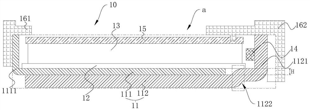
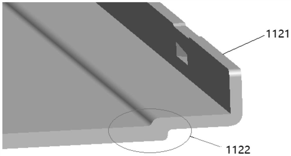
A backlight module comprises a back plate, a light source, a reflector plate, a light guide plate, an optical diaphragm and a fixing frame, wherein the back plate comprises a first bottom metal plateand a second bottom metal plate, a containing cavity is defined by the first bottom metal plate and the second bottom metal plate, the first bottom metal plate and the second bottom metal plate are compounded together through a riveting hole, and the first bottom metal plate is located on the upper surface of the second bottom metal plate; the light source is arranged in the containing cavity, andthe reflector plate is arranged on the bottom surface of the back plate; the light guide plate is arranged on the reflector plate, and the light emitting surface of the light source corresponds to the light incident surface of the light guide plate; the optical film is arranged in the containing cavity and is positioned on the light emitting surface of the light guide plate; the fixing frames arearranged on the two opposite sides of the back plate.

Description

technical field [0001] The present application relates to the field of display technology, in particular to a backlight module and a liquid crystal display module. Background technique [0002] With the development of vehicle-mounted display technology, the requirements for the appearance of vehicle-mounted display modules are getting higher and higher, and the requirements for the frame of vehicle-mounted LTPS (Low Temperature Poly-Silicon, LTPS, low temperature polysilicon) display modules are also getting narrower. [0003] Due to the high reliability requirements of the on-board display, the optical diaphragm will expand under high temperature conditions. Since the optical diaphragm of the vehicle-mounted display device is relatively large overall, the deformation due to expansion is also large. When the deformation of the optical diaphragm is greater than the gap between the optical diaphragm and the side wall, the optical diaphragm will be affected by The hindered exp...

Claims


Application Information

Patent Timeline
Patent Type & Authority Applications(China)
IPC IPC(8): G02F1/13357G02F1/1333G02B6/00
CPCG02F1/133608G02F1/133308G02B6/0088G02B6/009
Inventor 周政
Owner WUHAN CHINA STAR OPTOELECTRONICS TECH CO LTD
Why Eureka
Try Eureka