Display panel and display device

A technology for display panels and display areas, which is applied to electrical components, electrical solid-state devices, circuits, etc., and can solve the problems of occupying the display area of ​​the display panel, dense wiring at the edge of the punched area, and large edges of the punched area.

Active Publication Date: 2019-04-09
XIAMEN TIANMA MICRO ELECTRONICS
View PDF6 Cites 2 Cited by
  • Summary
  • Abstract
  • Description
  • Claims
  • Application Information

AI Technical Summary

Problems solved by technology

[0003] Since the punched area is located in the display area, when the various traces in the display panel extend to the punched area, they will continue to extend along the edge of the punched area, resulting in very dense traces on the edge of the punched area
Excessive traces lead to

Method used


Image

  • Display panel and display device
  • Display panel and display device
  • Display panel and display device

Examples


Embodiment Construction

[0029] In order to make the purpose, technical solution and advantages of the present invention clearer, the technical solution of the present invention will be fully described below through specific implementation in combination with the drawings in the embodiments of the present invention. Apparently, the described embodiments are some embodiments of the present invention, rather than all embodiments. Based on the embodiments of the present invention, all other embodiments obtained by persons of ordinary skill in the art without making creative efforts, All fall within the protection scope of the present invention.

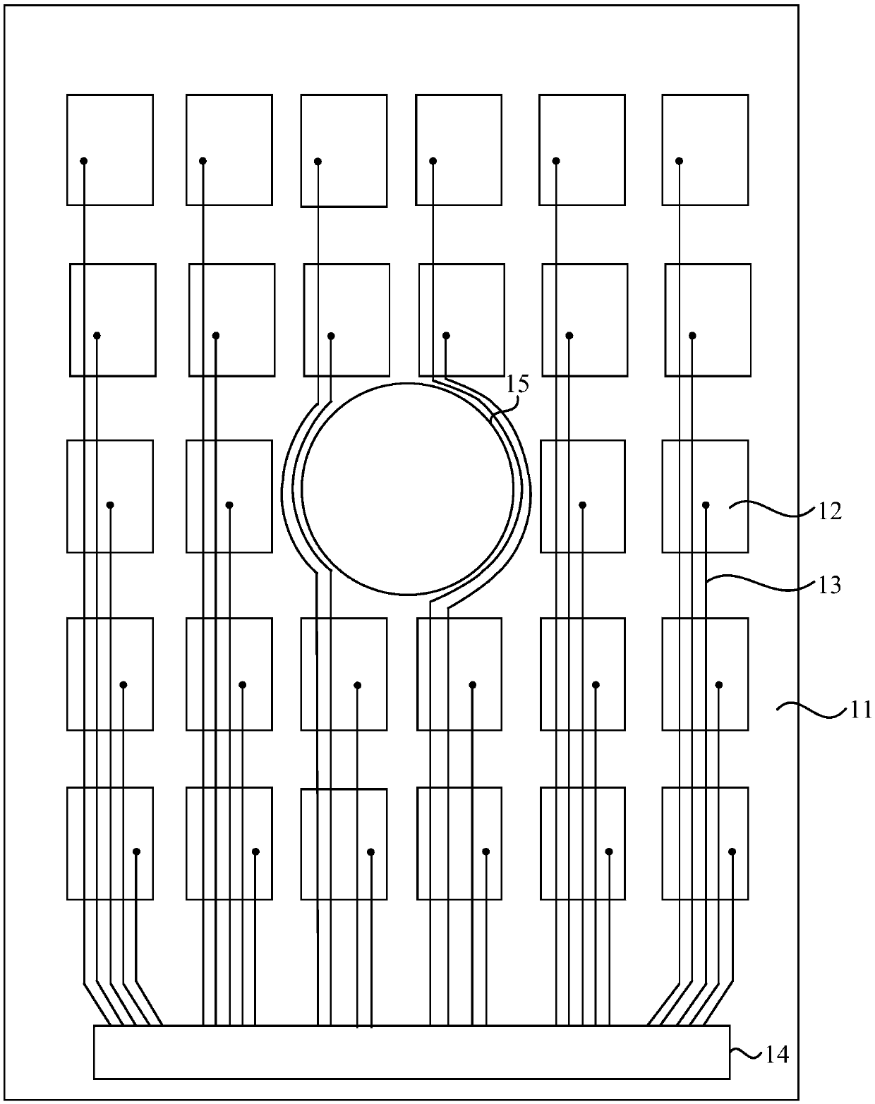
[0030] figure 1 It is a structural schematic diagram of a display panel in the prior art, such as figure 1 As shown, the display panel includes a substrate 11, a plurality of common electrodes 12 arranged in a matrix on one side of the substrate 11, a plurality of common signal traces 13, and an integrated driver IC 14. The display panel also includes through h...


PUM


Abstract

The invention discloses a display panel and a display device. The display panel comprises a common electrode, a plurality of common signal lines, a control chip and a common voltage line, wherein thecommon electrode comprises a first category of common electrodes and a second category of common electrodes; the common signal lines comprise a first category of common signal lines and a second category of common signal lines; the first end of the first category of common signal lines is electrically connected with the control chip, and the second end is electrically connected with the common electrode; and the first end of the second category of common signal lines is electrically connected with the common voltage line, and the second end is electrically connected with the common electrode except parts of first category of common electrodes between a through hole area and a first side. The common voltage line and the second common signal line are added to improve the display uniformity of the display panel; and the second end of the second category of common signal lines is electrically connected with the common electrode except parts of first category of common electrodes between the through hole area and the first side to reduce the amount of signal lines around the through hole area, reduce the area of the through hole area and improve the screen-to-body ratio of the display panel.

Description

technical field [0001] Embodiments of the present invention relate to the field of display technology, and in particular, to a display panel and a display device. Background technique [0002] With the development of the market, consumers have more and more stringent requirements for the display effect of the display screen. The full screen technology, through the design of ultra-narrow bezel or even no bezel, pursues a larger screen-to-body ratio. In this mode, the display area is maximized, and the display effect is even more stunning. Based on the structural design of the full screen, it is necessary to punch holes in the panel display area to install cameras, earpieces, sensors, etc. [0003] Since the perforated area is located in the display area, various traces in the display panel will continue to extend along the edge of the perforated area when extending to the perforated area, resulting in very dense traces at the edge of the perforated area. Excessive traces le...

Claims


Application Information

Patent Timeline
IPC IPC(8): H01L27/12
CPCH01L27/124
Inventor 孟垂玉周秀峰伍黄尧沈柏平
Owner XIAMEN TIANMA MICRO ELECTRONICS
Why Eureka
Try Eureka