
Ridge vent

A ventilator and roof ridge technology, which is applied in the field of roof ridge ventilators, can solve the problems of reducing the effective ventilation area, short length, and destroying the use of roof ridge ventilators.

Inactive Publication Date: 2019-08-27
斯诺文科有限公司
View PDF5 Cites 2 Cited by
  • Summary
  • Abstract
  • Description
  • Claims
  • Application Information

AI Technical Summary

Problems solved by technology

However, it is short in length and has to be pieced together
Also, due to the meniscus capillary force of the water in the open cells, the foam can hold moisture in the cells, reducing the effective ventilation area and thus defeating the purpose of the ridge vent.

Method used


Image

  • Ridge vent
  • Ridge vent
  • Ridge vent

Examples


Embodiment Construction

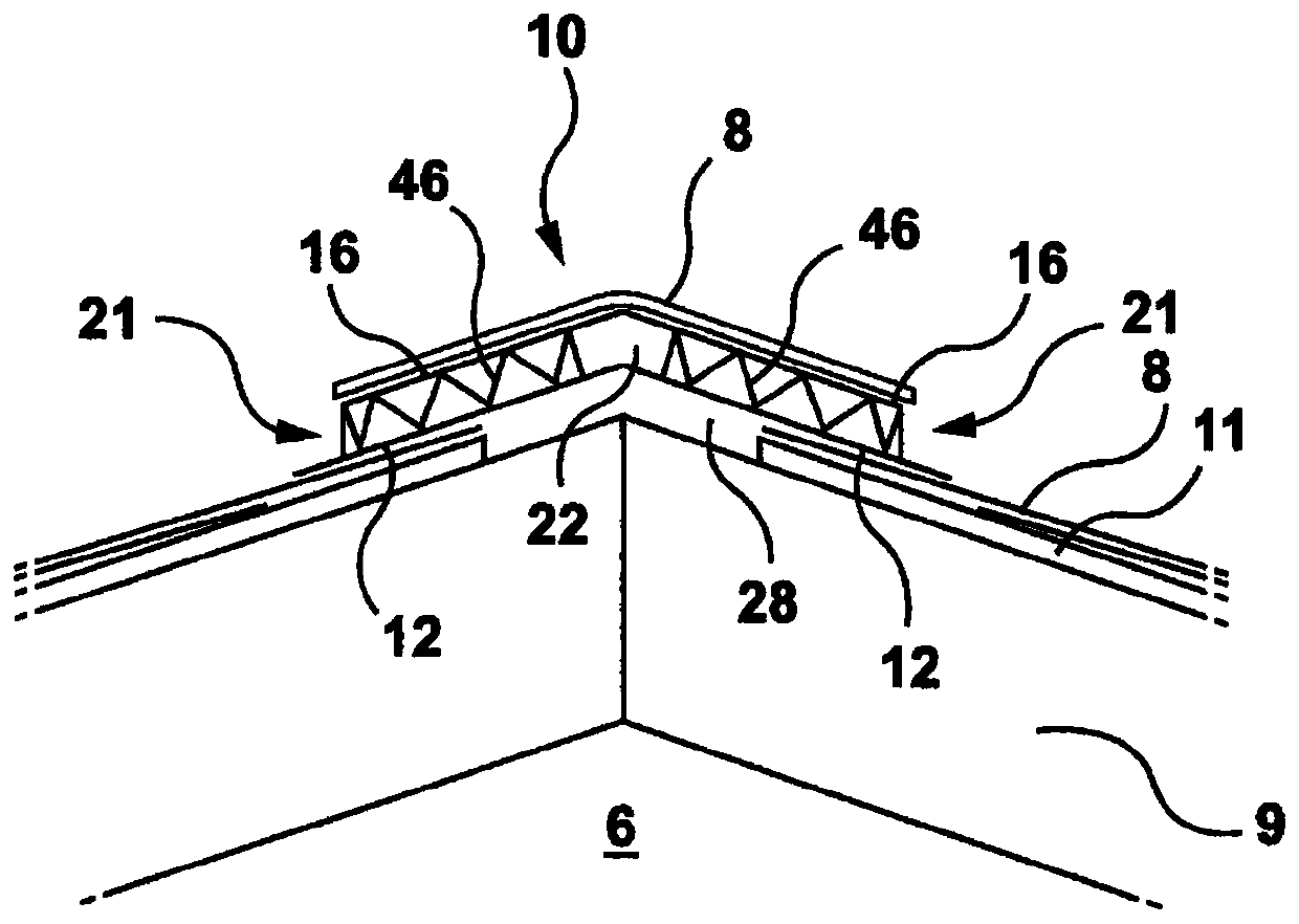
[0028] refer to figure 1 Ridge vent assembly 10 may include flanges 12 mounted along each side of roof 9, wherein flanges 12 sit atop or otherwise interweave roof panels 8. With this configuration, hot air in the attic space 6 can escape from the dwelling (i.e., the home) through the ridge vent assembly 10, especially in summer when the owner needs to cool the home and the attic space contains rather hot air. Sometimes, this provides the owner with a more energy-efficient construction and configuration. The ridge ventilator 10 for an asphalt shingle or composite roof is located above the ventilation slots 28 (ie holes) which are provided through the roof structure / roof shingle 11 along the ridge 9 .

[0029] The ridge vent assembly 10 is mounted as a series of interconnected (i.e. overlapping) angled panels 10a and 10b along the top of the roof 9 by a series of adjacent male and female joints 13a and 13b, see Figure 6 , so that the male connecting portion 13a is accommodat...


PUM


Abstract

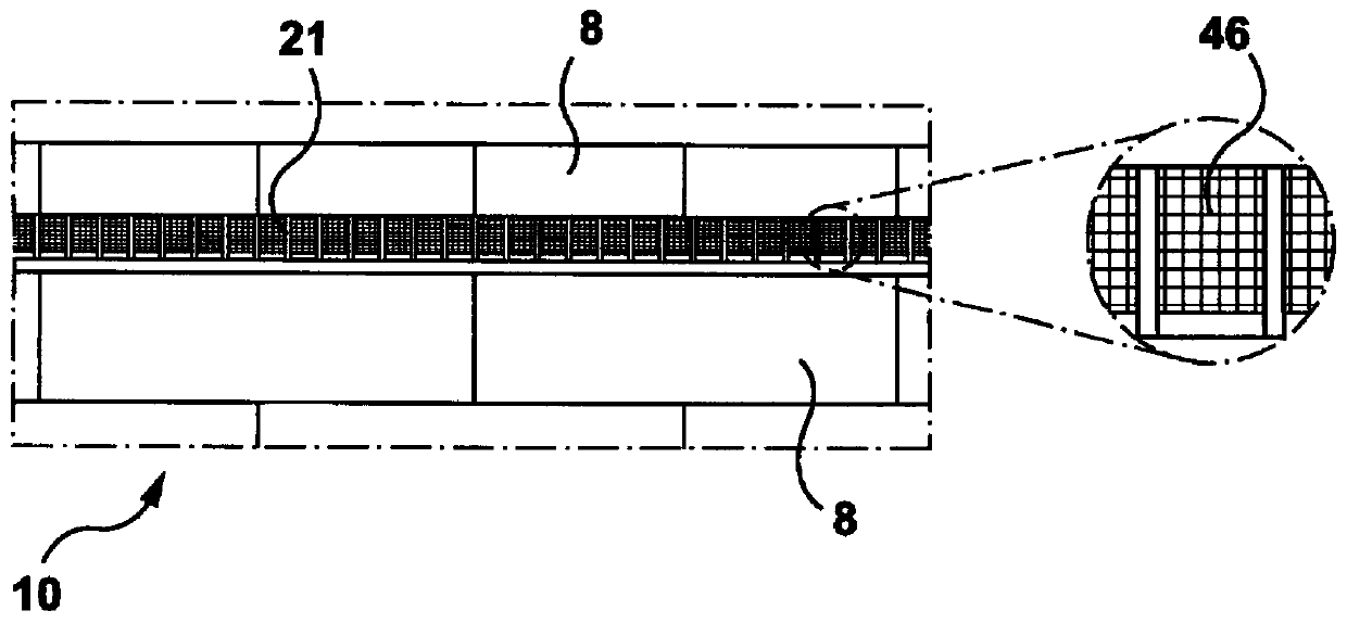
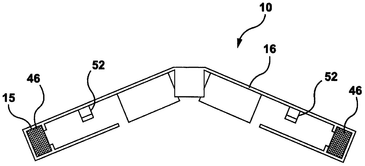
A ridge vent for ventilating a roof of a building via a hole along a roof ridge to atmosphere, the ridge vent comprising a first ridge vent panel: a flange portion for resting on the roof, the flangeportion having an opening for overlapping with the hole, the flange portion having a first flange portion positioned to one side of the opening and a second flange portion positioned to another side of the opening, such that the first flange portion and the second flange portion are at an acute angle with respect to one another; a frame portion coupled to the flange portion and having sides extending upwardly from the flange portion about the opening, the frame portion for maintaining a cap portion in a spaced apart relationship with the flange portion; the cap portion connected to the frame portion and covering over the opening; a first corrugated filter plate extending between the cap portion and the flange portion and positioned transversely between the opening and the atmosphere, the first corrugated filter plate positioned to said one side of the opening; and a second corrugated filter plate extending between the cap and the flange portion and positioned transversely between the opening and the atmosphere, the second corrugated filter plate positioned to said another side of the opening; wherein the corrugated filter plates providing for a passage of air between the atmosphereand the opening, the corrugated filter plates having a pore size sufficient for facilitating the air passage of air through the corrugated filter plates while blocking passage of atmospheric particles through the corrugated filter plates.

Description

[0001] Cross References to Related Applications [0002] This application claims priority to US Provisional Patent Application (Application No. 62 / 430,052), filed December 5, 2016; the entire contents of which are hereby incorporated by reference. technical field [0003] The present disclosure relates generally to ridge ventilators for ventilating the roof of buildings, such as houses. Background technique [0004] Ridge vents provide the necessary ventilation to the roof of a house or other structure and prevent condensation from forming on the roof due to moisture seeping through or otherwise collecting moisture into the roof or attic cavity. Various ridge vents are available with blades, grilles, filters and louvers to allow air to be directed along the ridge of the building between the roof and the atmosphere while trying to prevent rainwater from entering the roof through the vent. Various covers have been used as protection against the ingress of rainwater. However...

Claims


Application Information

Patent Timeline
Patent Type & Authority Applications(China)
IPC IPC(8): F24F7/02E04D13/17
CPCE04D13/174F24F13/28F24F7/02
Inventor 安托尼·博尔克
Owner 斯诺文科有限公司
Learn More