
Soil anchor rod drawing test method considering changing confining pressure conditions

A pull-out test and pull-out test technology, applied in the direction of applying stable tension/pressure to test the strength of materials, measuring devices, instruments, etc., can solve the problems of poor repeatability, large model size, and long construction period, etc., to achieve The test results are scientific and accurate, and the effect of improving precision

Inactive Publication Date: 2019-08-30
HEBEI INSTITUTE OF ARCHITECTURE AND CIVIL ENGINEERING
View PDF13 Cites 19 Cited by
  • Summary
  • Abstract
  • Description
  • Claims
  • Application Information

AI Technical Summary

Problems solved by technology

[0004] If the in-situ test is used to analyze and test the dynamic anchoring performance of the anchor when the stress state of the soil and the strength and size of the anchor are changed, there are problems such as high cost, long construction period, and multi-working condition analysis cannot be carried out. The evaluation of performance is not systematic and objective enough
Carrying out model tests in the trenches and model boxes has defects such as large model size, poor repeatability, and inability to guarantee soils with different stress states.

Method used


Image

  • Soil anchor rod drawing test method considering changing confining pressure conditions
  • Soil anchor rod drawing test method considering changing confining pressure conditions
  • Soil anchor rod drawing test method considering changing confining pressure conditions

Examples


Embodiment Construction

[0055] Below, the present invention is described in detail with reference to accompanying drawing and embodiment:

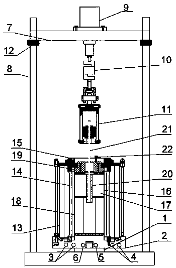
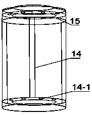
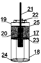
[0056] Such as Figure 1~6 As shown, a soil anchor pullout test method considering changing confining pressure conditions includes the following steps:

[0057] ⅰ. Install the lower gasket and support base

[0058] First install the lower gasket 1 at the support platform, and then install the support base 2 of the anchor pullout test device on the upper end of the lower gasket 1;

[0059] ⅱ. Install the valve on the outer wall of the support base

[0060] Install the water inlet valve 3, drain valve 4, pore pressure connection valve 5, and confining pressure connection valve 6 in the test at the interface of the outer wall of the support base 2 in sequence according to the corresponding positions;

[0061]ⅲ. Install the sample base, test sample, sample cap and ensure the tightness

[0062] Install the height-adjustable sample base 18 on the support base 2 of ...


PUM


Abstract

The present invention discloses a soil anchor rod drawing test method considering changing confining pressure conditions. The method comprises: installing a lower gasket and a supporting base; installing a valve at an outer wall of the supporting base; installing a sample base, a test sample, and a sample cap and ensuring sealing performance; installing a reaction force frame and a reaction forceframe upper cover on outside of the test sample and the sample cap; injecting water and pressurizing an environmental pressure chamber of the sample to simulate stress state of the soil; adjusting height of the reaction force beam and connecting and clamping an anchor rod; dynamic loading shock loads borne by a simulated anchor, and recording experimental data; and disassembling an anchor rod drawing test device. The method applies confining pressure around the test sample to effectively simulate the actual stress state of the soil body, at the same time, has a dynamic loading device system atthe reaction force beam, can realize dynamic drawing of the anchor rod, and more truly reflects the stress and deformation of the anchor rod in an actual project. The method improves precision of anexperimental test and makes test results more scientific and accurate

Description

technical field [0001] The invention belongs to the technical field of rock and soil anchoring engineering, and in particular relates to a soil anchor pullout test method considering changing confining pressure conditions. Background technique [0002] With the vigorous development of many engineering constructions in our country, geotechnical anchoring technology has played an important role in it. Bolt support is an important part of geotechnical anchoring technology. Because of its economical, effective, safe and reliable reinforcement characteristics, it has been widely used in engineering construction and has great development prospects. The anchoring technology relies on the tight bonding between the rod body and the surrounding rock and soil to improve the strength and stability of the soil. If it can be effectively anchored in the soil layer, it depends on the resistance of the anchor rod to be pulled out. After research, it is found that the force and deformation o...

Claims


Application Information

Patent Timeline
Patent Type & Authority Applications(China)
IPC IPC(8): G01N3/08
CPCG01N3/08G01N2203/0017G01N2203/0676G01N2203/0682
Inventor 董捷杨云仲帅许鹏飞杨博李成献赵聪王志岗孙京华
Owner HEBEI INSTITUTE OF ARCHITECTURE AND CIVIL ENGINEERING
Learn More