Supercharge Your Innovation With Domain-Expert AI Agents!

AC line detection and X capacitor discharge using a single terminal

A technology for detecting circuits and terminals, which is applied in the direction of electrical components, circuit devices, battery circuit devices, etc., and can solve the problems of increasing the manufacturing cost of the controller U1

Active Publication Date: 2019-09-03
DIALOG SEMICONDUCTOR
View PDF4 Cites 0 Cited by
  • Summary
  • Abstract
  • Description
  • Claims
  • Application Information

AI Technical Summary

Problems solved by technology

Each additional pin increases the manufacturing cost of the controller U1

Method used


Image

  • AC line detection and X capacitor discharge using a single terminal
  • AC line detection and X capacitor discharge using a single terminal
  • AC line detection and X capacitor discharge using a single terminal

Examples


Embodiment Construction

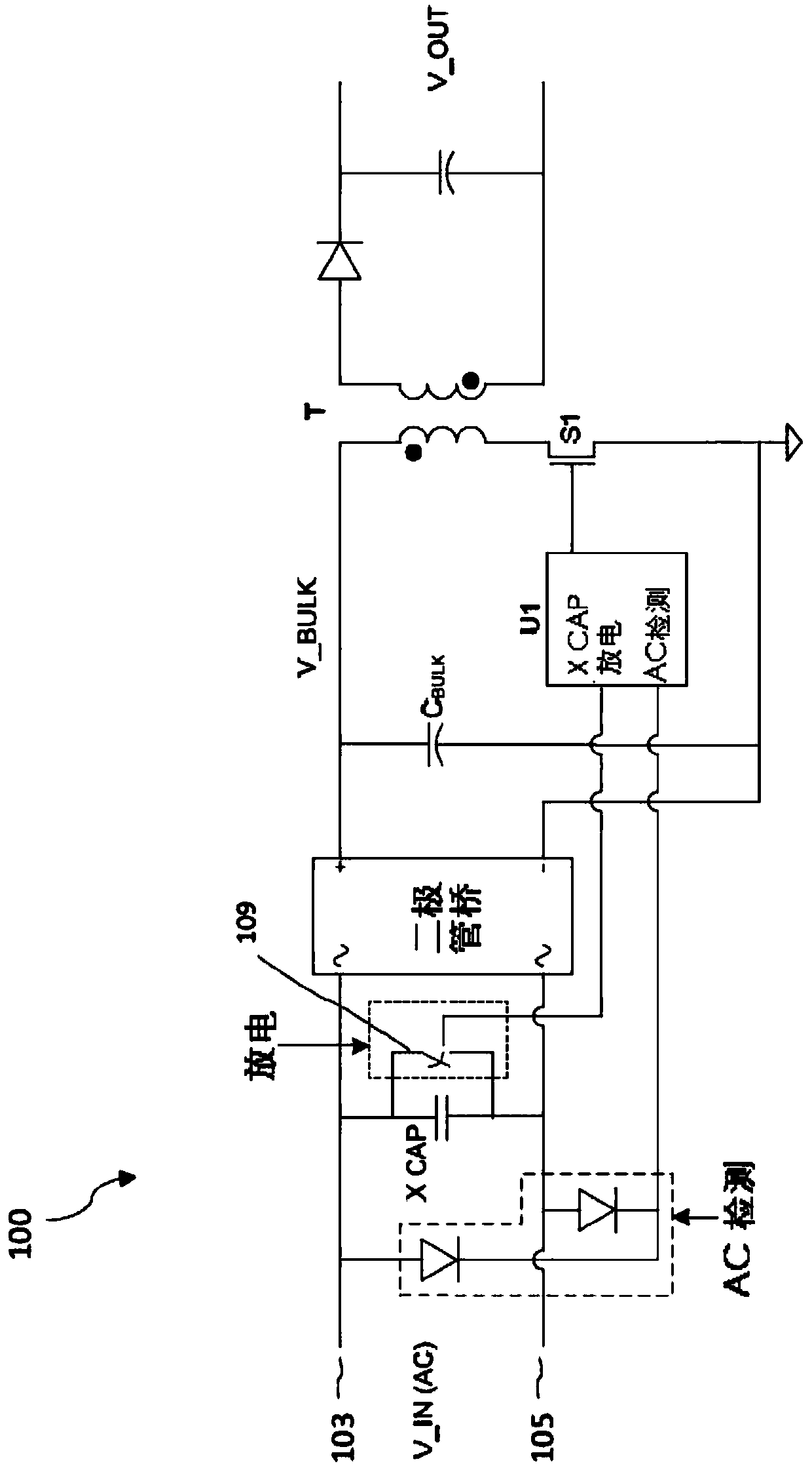
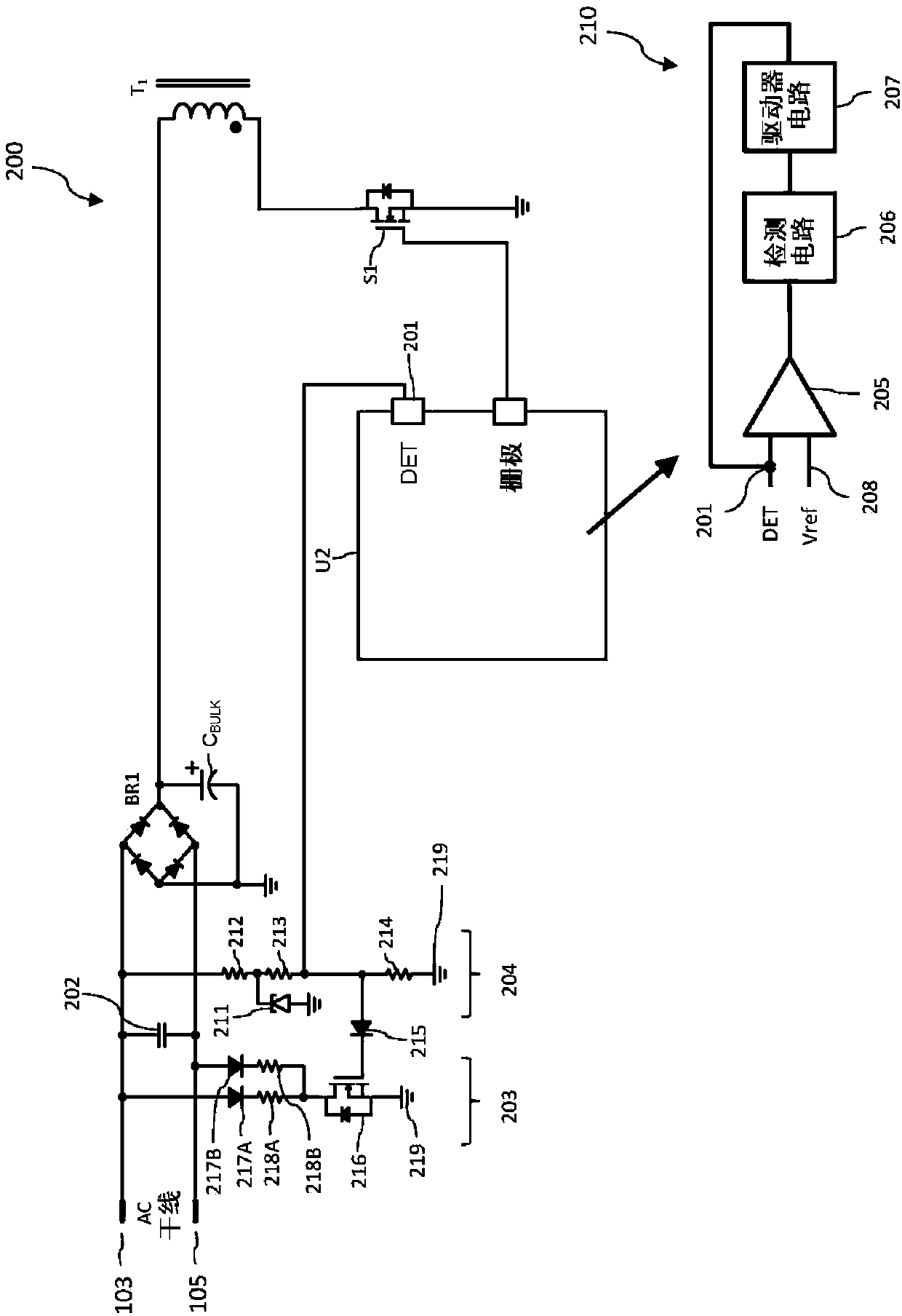
[0012] The following discussion will be directed to a flyback converter embodiment. It will be appreciated, however, that the single-pin AC detection and X-capacitor discharge control disclosed herein can be implemented in other types of switching power converters, such as buck converters, boost converters, or buck-boost converters. exist figure 2 An example flyback converter 200 with a controller U2 configured for single-pin AC detection and X-capacitor discharge is shown in . as about figure 1 As discussed, the flyback converter 200 includes a power switching transistor S1 connected in series with the primary winding of the transformer T. Controller U2 controls the cycling of power switching transistor S1 to regulate the output voltage through the gate pin or terminal (GATE) (for clarity, in figure 2 The secondary side of the transformer T is not shown). For clarity of illustration, additional components of flyback converter 200 , such as a sense resistor, are not show...


PUM


Abstract

A controller for a switching power converter is provided with a single detection pin through which the controller monitors whether the switching power converter is connected to an AC mains. Should a voltage for the detection pin indicate that the switching power converter is disconnected from the AC mains, the controller asserts the detection pin voltage to trigger a bleeder circuit to discharge an X class capacitor.

Description

technical field [0001] The present application relates to switching power converter controllers, and more particularly to switching power converter controllers with AC detection and filter capacitor discharge control. Background technique [0002] The high efficiency of switching power converters has led to their almost universal suitability for powering and charging mobile devices. Because switching power converters (power adapters) switch at frequencies as high as one hundred kilohertz or even higher, the power adapter can drive high frequency noise onto the AC mains. To prevent this undesirable noise from affecting the AC mains, power adapters typically include a high frequency filter capacitor (indicated as an X-type capacitor or X-capacitor) connected across the AC line terminal (AC live) and the AC neutral terminal. The voltage on the AC line terminals will oscillate according to the oscillating frequency of the AC mains with respect to the AC neutral terminal voltage...

Claims


Application Information

Patent Timeline
IPC IPC(8): H02M1/00
CPCH02M1/00H02M1/322H02M1/126H02J7/02H02J2207/20H02M5/293H02M5/12
Inventor 冯光施琦锋喻江沙璆Y·X·林
Owner DIALOG SEMICONDUCTOR
Features
  • R&D
  • Intellectual Property
  • Life Sciences
  • Materials
  • Tech Scout
  • Unparalleled Data Quality
  • Higher Quality Content
  • 60% Fewer Hallucinations
Learn More