Air conditioner for vehicle
A technology for air-conditioning devices and vehicles, which can be used in vehicle components, applications, household heating, etc., and can solve problems such as the inability to filter and the decline in the collection capacity
- Summary
- Abstract
- Description
- Claims
- Application Information
AI Technical Summary
Problems solved by technology
Method used
Image
Examples
no. 1 approach >
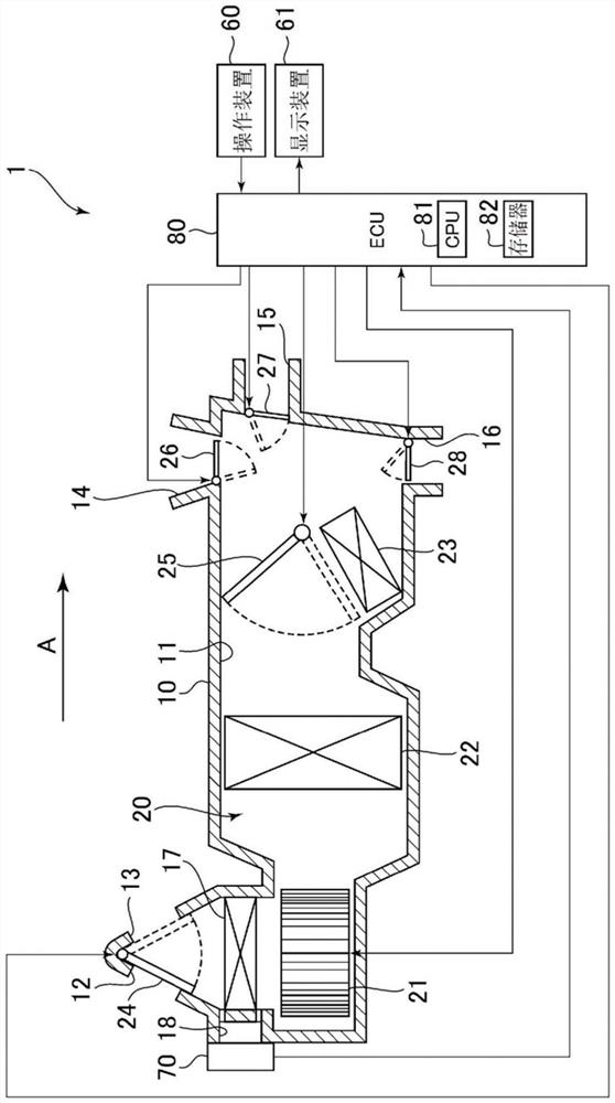
[0026] First, the first embodiment of the vehicle air conditioner will be described.
[0027] like figure 1 As shown, the vehicle air conditioner 1 of the present embodiment includes an air conditioner duct 10 and an air conditioner unit 20 . The vehicle air conditioner 1 is provided inside a dashboard of a vehicle.
[0028] Inside the air-conditioning duct 10, an air passage 11 is formed, and the air passage 11 guides the air-conditioning wind for air-conditioning the vehicle interior into the vehicle interior. In the air passage 11, the air flows in the direction indicated by the arrow A in the figure. An outside air intake port 12 and an inside air intake port 13 are formed in a portion on the upstream side of the air conditioning duct 10 in the air flow direction A as a portion for taking in air from the outside of the air conditioning duct 10 into the air passage 11 . The outside air intake port 12 is a portion that takes outside air, which is the air outside the vehic...
no. 2 approach >
[0087] Next, a second embodiment of the vehicle air conditioner 1 will be described. Hereinafter, the difference from the first embodiment will be mainly described.
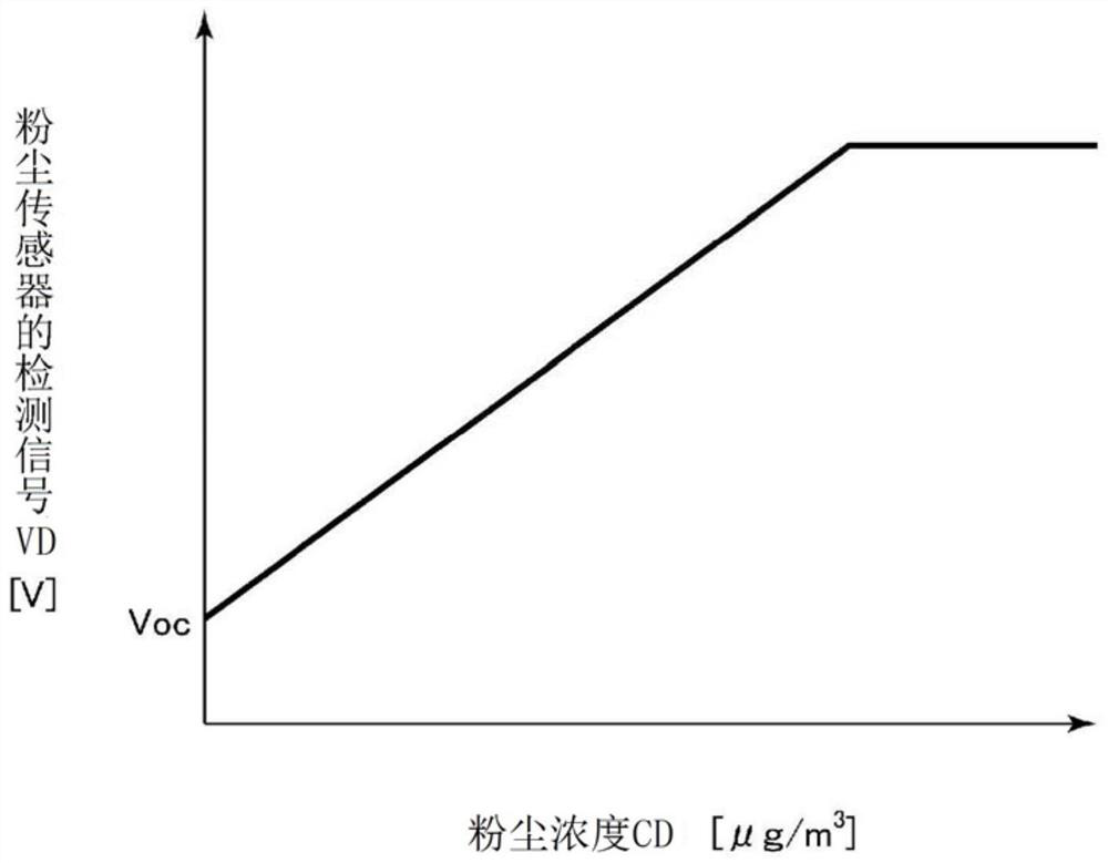
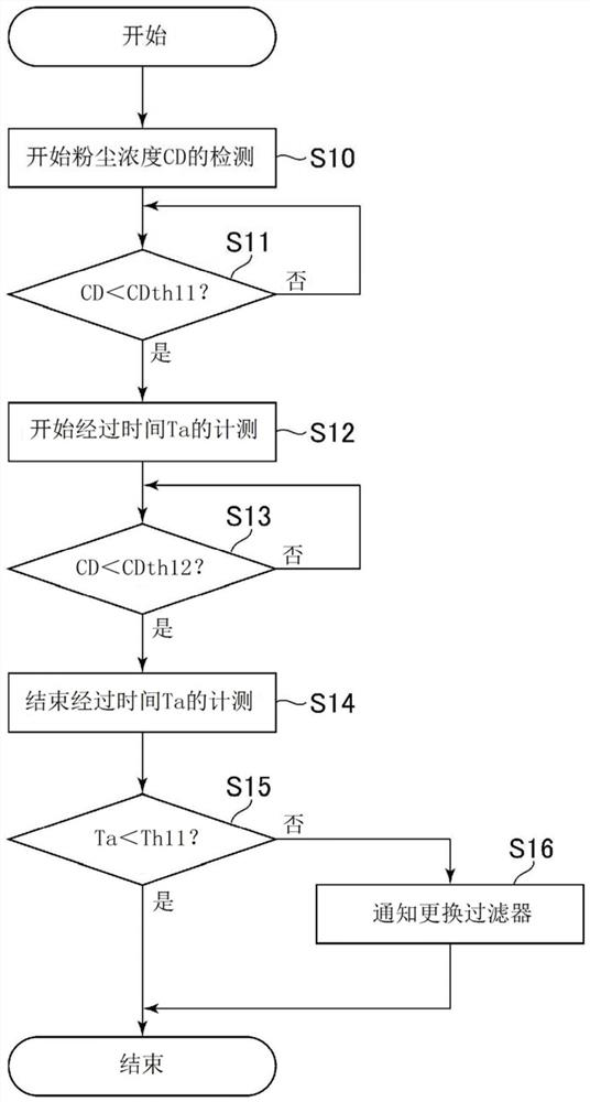
[0088] The ECU 80 of the present embodiment replaces image 3 The shown filter capability determination process is executed when the vehicle air conditioner 1 starts to operate Figure 8 The filter capability determination process shown. That is, first, as the process of step S30 , the ECU 80 detects the first dust concentration CD20 based on the detection signal VD of the dust sensor 70 . The first dust concentration CD20 is the dust concentration detected by the dust sensor 70 when the operation of the vehicle air conditioner 1 is started. After that, the ECU 80 starts the measurement of the elapsed time Ta as a process of step S31. That is, the ECU 80 starts the measurement of the elapsed time Ta from the time when the first dust concentration CD20 is detected. Next, as the process of step S32, the ECU 80...
no. 3 approach >
[0100] Next, a third embodiment of the vehicle air conditioner 1 will be described. Hereinafter, the difference from the first embodiment will be mainly described.
[0101] The ECU 80 of the present embodiment replaces image 3 The shown filter capability determination process is executed when the operation of the vehicle air conditioner 1 starts Figure 10 The filter capability determination process shown. That is, first, as the process of step S40, the ECU 80 starts detection of the dust concentration CD40 based on the detection signal VD of the dust sensor 70, and starts the measurement of the elapsed time Ta as the process of step S41.
[0102] Thereafter, as a process of step S42, the ECU 80 determines whether or not the elapsed time Ta has exceeded the predetermined time Tth31. When an affirmative determination is made in the process of step S42, that is, when the elapsed time Ta exceeds the predetermined time Tth31, as the process of step S43, the ECU 80 determines t...
PUM
 Abstract
Description
Claims
Application Information
 - R&D
- Intellectual Property
- Life Sciences
- Materials
- Tech Scout
- Unparalleled Data Quality
- Higher Quality Content
- 60% Fewer Hallucinations
Browse by: Latest US Patents, China's latest patents, Technical Efficacy Thesaurus, Application Domain, Technology Topic, Popular Technical Reports.
© 2025 PatSnap. All rights reserved.Legal|Privacy policy|Modern Slavery Act Transparency Statement|Sitemap|About US| Contact US: help@patsnap.com


