
Eureka
For R&D, Eureka makes reading and utilizing patents & technical documents easy.
Eureka AIR
Designed for self-driven R&D workflows. Generate viable solutions, solve complex R&D challenges, empower your innovation with AI.

Eureka Materials
Designed for material experts only. Revolutionize your material R&D, from search, analyze, to developing new materials.

TechResearch
Generate reliable direction feasibility study reports for your R&D in just a few steps.

TechSeek
Discover and master advanced knowledge NOW. Basics, ideas, possibilities, all at once.

TechMind
As an expert in R&D Theories, TechMind can generates customized viable solutions instantly.

TechRisk
Analyze your overall solution with one click, know your potential R&D risks in advance.

TechMonitor
Get weekly tech updates, stay abreast of the latest tech innovations and key insights.
Split fitness equipment
A technology of fitness equipment and movable boards, applied in sports accessories, gymnastics equipment, etc., can solve the problems of high labor cost, difficulty in stretching, and inability to know the stretching limit of the trainer
- Summary
- Abstract
- Description
- Claims
- Application Information
AI Technical Summary
Problems solved by technology
Method used
Image

Examples
Embodiment 1
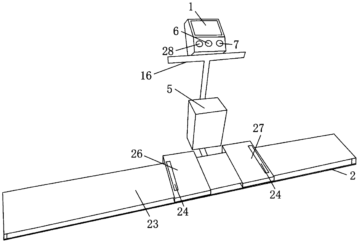
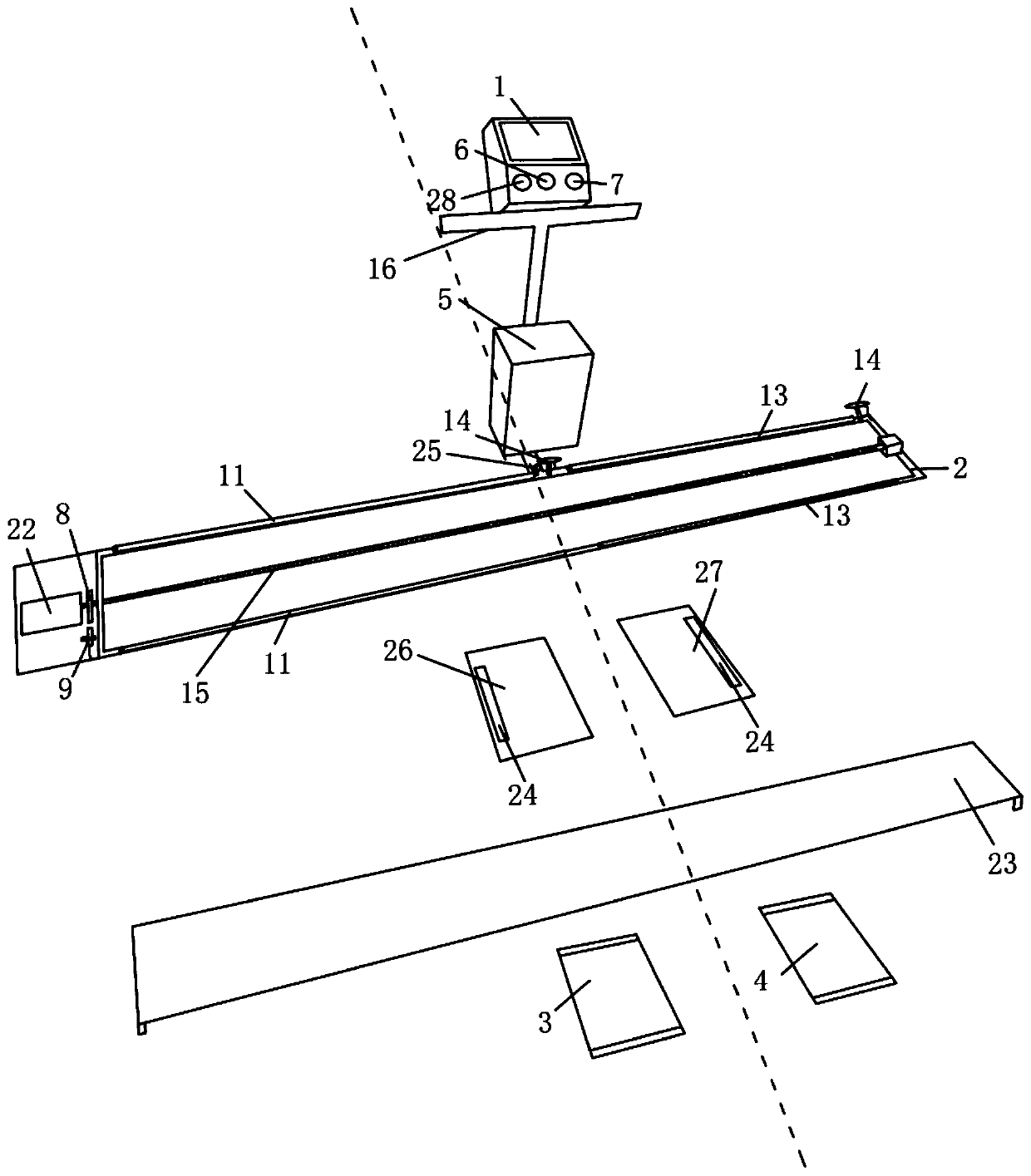
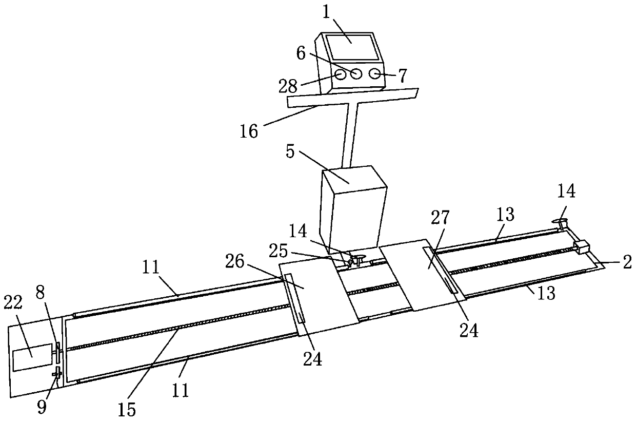
[0028] see Figure 1 to Figure 7 Shown, a kind of fitness equipment for a horse, comprising a control mechanism, a touch panel 1, a fixed frame 2, a left movable plate 3 that is movably arranged on the fixed frame 2, a right movable plate 4 that is movably arranged on the fixed frame 2, and used for Drive the left movable panel 3 and the right movable panel 4 to move toward each other or drive the drive mechanism for the relative movement of the left movable panel 3 and the right movable panel 4, and a power supply 5 for powering the control mechanism, the touch panel 1 and the drive mechanism; the touch panel 1 is connected with the signal of the control mechanism, and the control mechanism is connected with the signal of the driving mechanism; the fixed frame 2 is provided with a protective plate 23, and both ends of the left movable plate 3 protrude from the protective plate 23, and both ends of the right movable plate 4 protrude from the Protective plate 23, the two ends o...
Embodiment 2
[0041] Such as Figure 8 As shown, different from Embodiment 1, the transmission member includes a first gear 17, a second gear 18 and a chain 19, the motor 22 is arranged at one end of the fixed frame 2, the first gear 17 is connected to the output end of the motor 22, and the second gear 17 is connected to the output end of the motor 22. Two gears 18 are arranged on the other end of fixed mount 2, and first gear 17 and second gear 18 all mesh with chain 19, and left movable plate 3 is fixed on the top of chain 19, and right movable plate 4 is fixed on the bottom of chain 19. Specifically, when the motor 22 drives the first gear 17 to rotate, it drives the second gear 18 and the chain 19 to rotate. At this time, the upper part of the chain 19 and the lower part of the chain 19 move in opposite directions to realize the left movable plate 3 and the right movable plate 4. Simultaneously move toward each other or relative to each other. Specifically, at least one third gear is ...
Embodiment 3
[0043] Different from Embodiment 1 and Embodiment 2, the transmission member includes a first synchronous gear, a second synchronous gear and a synchronous belt, the motor 22 is arranged at one end of the fixed frame 2, and the first synchronous gear is connected to the output end of the motor 22. The second synchronous gear is arranged on the other end of the fixed frame 2, the first synchronous gear and the second synchronous gear are connected with the synchronous belt in rotation, the left movable plate 3 is fixed on the upper part of the synchronous belt, and the right movable plate 4 is fixed on the lower part of the synchronous belt . Specifically, when the motor 22 drives the first synchronous gear to rotate, it drives the second synchronous gear and the synchronous belt to rotate. At this time, the upper part of the synchronous belt and the lower part of the synchronous belt move in opposite directions, realizing the left movable plate 3 and the right movable plate 4. ...
PUM
 Abstract
Description
Claims
Application Information
 - R&D Engineer
- R&D Manager
- IP Professional
- Industry Leading Data Capabilities
- Powerful AI technology
- Patent DNA Extraction
Browse by: Latest US Patents, China's latest patents, Technical Efficacy Thesaurus, Application Domain, Technology Topic, Popular Technical Reports.
© 2024 PatSnap. All rights reserved.Legal|Privacy policy|Modern Slavery Act Transparency Statement|Sitemap|About US| Contact US: help@patsnap.com