
A Robot Target Trajectory Accuracy Compensation Method for Industrial Measurement

A target trajectory and industrial measurement technology, applied in the field of robotics, can solve problems such as space coordinate measurement value deviation, measurement data overall deviation, and affecting detection accuracy, and achieve the effect of improving measurement positioning accuracy

Active Publication Date: 2022-07-19
WUHAN INSTITUTE OF TECHNOLOGY
View PDF7 Cites 0 Cited by
  • Summary
  • Abstract
  • Description
  • Claims
  • Application Information

AI Technical Summary

Problems solved by technology

However, in this invention, the industrial robot performs measurement based on the trajectory generated by offline programming. During the measurement, the robot may not be able to accurately reach the expected pose.
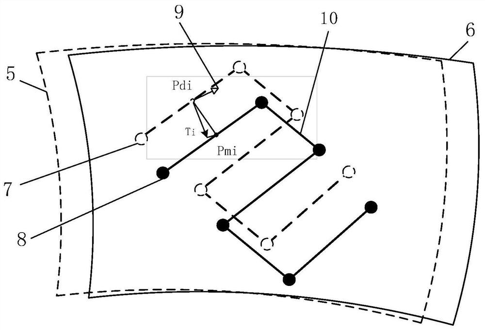
On the one hand, due to the positioning error of the workpiece installation, the overall deviation of all measurement data will appear, and the absolute positioning error of the robot will cause the position of the end point of the industrial robot to execute the trajectory program file to deviate from the planned point. This error is called It is the superposition of local errors, which will lead to a large deviation in the measured value of the spatial coordinates of the real measurement point corresponding to the feature point. The size and tolerance analysis of the product based on the measurement point will cause systematic errors and affect the final detection accuracy.

Method used


Image

  • A Robot Target Trajectory Accuracy Compensation Method for Industrial Measurement
  • A Robot Target Trajectory Accuracy Compensation Method for Industrial Measurement
  • A Robot Target Trajectory Accuracy Compensation Method for Industrial Measurement

Examples


Embodiment Construction

[0032] The present invention will be further described below with reference to specific examples and accompanying drawings.

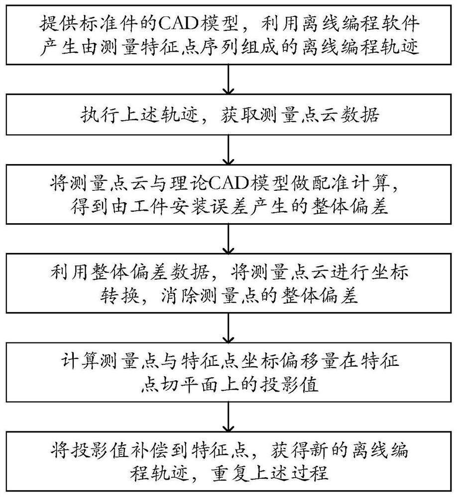
[0033] like figure 1 As shown, the present invention provides a robot target trajectory accuracy compensation method for industrial measurement, comprising the following steps:

[0034] Step 1: Provide the CAD model of the standard part according to the detection process requirements (the actual product shape is consistent with the CAD model), and then use the offline programming software to generate an offline programming track consisting of a sequence of measured feature points {P d_i }.

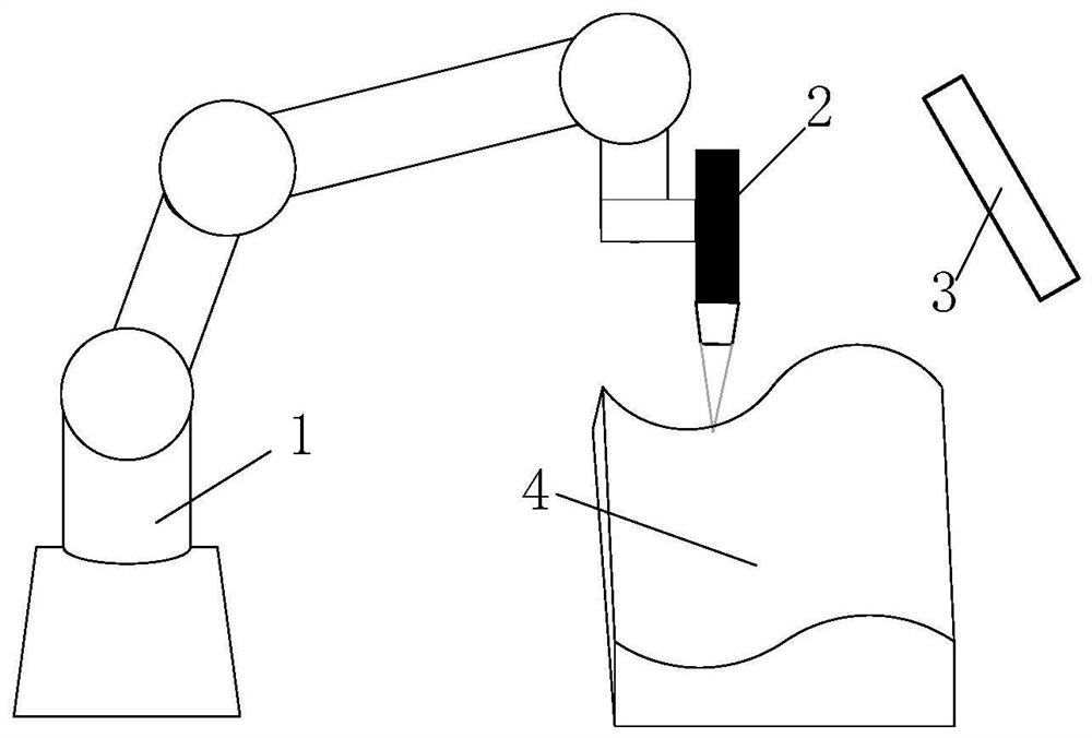
[0035] Step 2: In the measurement station, transmit the trajectory generated in step 1 to the robot control unit, control the robot to execute the trajectory, and obtain the measurement point cloud data (actually an ordered measurement point set) {P m_j }; During the movement of the robot, when the robot executes the measurement command of the point to be measured...


PUM


Abstract

The invention provides a robot target trajectory accuracy compensation method for industrial measurement, which provides a CAD model of a standard part according to a detection process requirement to generate an offline programming trajectory; the robot executes the offline programming trajectory to obtain a measurement point cloud; in the workpiece coordinate system, Perform the registration calculation of the measurement point cloud and the CAD model to obtain the overall deviation due to the workpiece installation error; coordinate the measurement point cloud to eliminate the overall deviation of the measurement point, and unify the feature points and measurement points to the workpiece coordinate system Next, for each feature point of the offline programming trajectory, calculate the projection point on the curve formed by the measurement point; calculate the projection of the coordinate offset on the tangent plane of the feature point; compensate the projection to the feature point to obtain a new Offline programming trajectory; until the projection converges to a certain range of target measurement accuracy, the target trajectory compensation is completed. The invention is beneficial to improve its measurement and positioning accuracy.

Description

technical field [0001] The invention belongs to the technical field of robots, and in particular relates to a robot target trajectory accuracy compensation method for industrial measurement. Background technique [0002] For the shape measurement of batch industrial parts, the usual solution is to convert the detection requirements for dimensions or contours into the measurement of the spatial coordinates of a series of feature points, and then perform tolerance analysis based on the coordinate measurement results of the feature points. [0003] For the measurement accuracy of about 0.1mm, such as the shape detection of body panels and glass products used in automobiles, it is still impossible to directly use robots to build an automatic detection system. The reason is that although the repeatability of industrial robots However, due to the relatively low absolute spatial accuracy, which can only be up to 0.5mm level, it cannot be used for precision detection requirements be...

Claims


Application Information

Patent Timeline
Patent Type & Authority Patents(China)
IPC IPC(8): B25J9/16
CPCB25J9/1605B25J9/1664
Inventor 颜昌亚万炜强刘磊黄昆涛何姗姗李振瀚
Owner WUHAN INSTITUTE OF TECHNOLOGY
Learn More