Lock-up control for torque converter

Active Publication Date: 2005-10-06
NISSAN MOTOR CO LTD
View PDF28 Cites 25 Cited by
  • Summary
  • Abstract
  • Description
  • Claims
  • Application Information

AI Technical Summary

Benefits of technology

[0007] It is therefore an object of this invention to rapidly learn a differential pressure while takin

Problems solved by technology

However, in the aforesaid prior art, when lock-up is performed during coasting of the vehicle (when the accelerator pedal stroke is zero), learning is performed after decreasing the front-rear differential pressure of the lock-up clutch until a small slip occurs, and unless coasting of the vehicle is continued for a long time, the differential pressure learning value is not appropriate.
For example, if the real differential pressure is larger than a differe

Method used


Image

  • Lock-up control for torque converter
  • Lock-up control for torque converter
  • Lock-up control for torque converter

Examples


Embodiment Construction

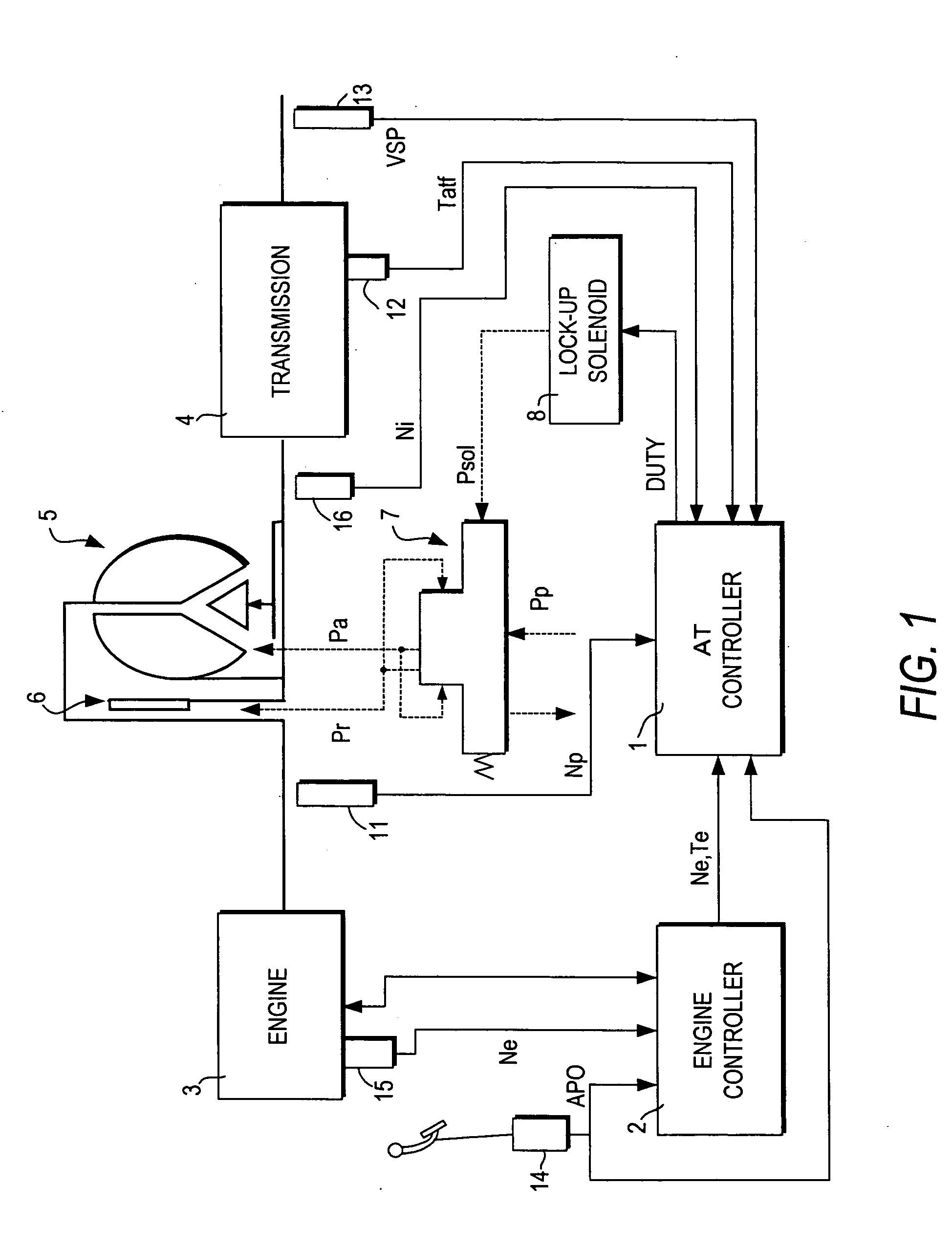
[0018] An automatic transmission comprising a torque converter 5 and a transmission 4 is connected to an engine 3. The torque converter 5 is provided with a lock-up clutch 6, the lock-up clutch 6 being in a lock-up state (engaged state) or unlocked state (release state) according to the vehicle running state.

[0019] The torque converter 5 houses the lock-up clutch which rotates with a torque converter output element (i.e. turbine). When the lock-up clutch 6 is directly connected to a torque converter input element (i.e. impeller), the torque converter 5 enters a lock-up state wherein the input and output elements are engaged by the lock-up clutch 6.

[0020] The lock-up clutch 6 responds to a differential pressure Pa—Pr between the torque converter apply pressure Pa and torque converter release pressure Pr on front and rear sides thereof. When the release pressure Pr is higher than the apply pressure Pa, the lock-up clutch 6 is released and the torque converter input and output elemen...


PUM


Abstract

A lock-up clutch control device which controls a lock-up clutch provided in a torque converter installed between an engine and a transmission, is disclosed. The lock-up clutch control device changes over between a converter state and a lock-up state of the torque converter according to a differential pressure command value (LUprs) relating to a differential pressure supplied to the lock-up clutch. The lock-up clutch control device includes a differential pressure generating device (7,8) which generates the differential pressure supplied to the lock-up clutch; input torque detection means (2,14,15) which detects an input torque (Te) to the torque converter; and a controller (1). The controller (1) is programmed to compute a real differential pressure (P_lu) based on the detected input torque (Te) upon completion of the engagement of the lock-up clutch; compute a learning value (P_learn(Tai)) relating to a differential pressure deviation, based on the difference between the computed real differential pressure (P_lu) and differential pressure command value (P_ref) upon completion of the engagement of the lock-up clutch, and store the learning value (P_learn(Tai)); correct a present differential pressure command value (LUprs_slp) based on the learning value (P_learn(Tai)); and send the corrected differential pressure command value (LUprs) to the differential pressure generating device (7, 8).

Description

FIELD OF THE INVENTION [0001] This invention relates to a control device for controlling lock-up of a torque converter. BACKGROUND OF THE INVENTION [0002] In a torque converter provided with a lock-up clutch, control of a front-rear differential pressure (lock-up differential pressure) of the lock-up clutch engages and releases the lock-up clutch. To shift the torque converter from a converter state to a lock-up state, the lock-up differential pressure gradually increases from a predetermined initial differential pressure. The torque converter shifts from the converter state to the lock-up state via a slip state. In the converter state the lock-up clutch is released, in the slip state the lock-up clutch slips, and in the lock-up state, the lock-up clutch is engaged. [0003] In this lock-up clutch control, the real lock-up clutch differential pressure has scatter due to individual differences and time-dependent variations of the torque converter. JP2000-27986 published by the Japan Pa...

Claims


Application Information

Patent Timeline
IPC IPC(8): F16H59/14F16H61/14F16H61/00G06F7/00
CPCF16H59/14F16H61/143F16H2061/0087F16H2059/147Y10T477/70Y10T477/638Y10T477/32
Inventor IMAMURA, TATSUYASEKIYA, HIROSHIIIDA, TOSHIJIDOHI, KOJISEGAWA, SATOSHI
Owner NISSAN MOTOR CO LTD
Why Eureka
Try Eureka