
Automatic bolt lock for side hung door and side hung door

A technology of side-hung doors and bolt locks, applied in the field of access control, which can solve the problems of door closing obstacles, entry of sand, stones or other objects, manual operation of opening and closing doors, etc., and achieve the effect of preventing deformation

Pending Publication Date: 2019-09-06
JIANGXI BAISHENG GATE & DOOR AUTOMATION
View PDF0 Cites 2 Cited by
  • Summary
  • Abstract
  • Description
  • Claims
  • Application Information

AI Technical Summary

Problems solved by technology

This solution can only limit the movement of the end of the swing door, and every time the door is opened and closed, manual operation is required, which is very inconvenient
[0003] In the existing electric bolt lock, after the bolt stroke is set, it is generally not adjustable. When stones or other obstacles on the ground are encountered during the locking process, the motor will be blocked, and the base hole on the ground will inevitably enter Sand, stones or other objects, frequent stalls may damage the motor
Secondly, after long-term use, due to the self-weight of the door body, the cantilever end will be deformed, causing the end to sink, and in severe cases, it may cause obstacles to closing the door
In addition, most of the latch locks do not have a self-locking function. When the latch is locked normally, tools can be used to pry the latch to unlock it, which is less secure.

Method used


Image

  • Automatic bolt lock for side hung door and side hung door
  • Automatic bolt lock for side hung door and side hung door
  • Automatic bolt lock for side hung door and side hung door

Examples


Embodiment Construction

[0037] It should be noted that the terms "vertical", "horizontal", "left", "again", "upper", "lower" and similar expressions are used for the purpose of description only, not to indicate or imply The devices or elements referred to must have a specific orientation, configuration and operation and therefore should not be construed as limiting the invention.

[0038] In the present invention, unless otherwise clearly specified and limited, terms such as "installation", "connection", "connection" and "fixation" should be understood in a broad sense, for example, it can be a fixed connection or a detachable connection , or integrally connected; may be mechanically connected, may also be electrically connected; may be directly connected, may also be indirectly connected through an intermediary, and may be internal communication between two components. Those of ordinary skill in the art can understand the specific meanings of the above terms in the present invention according to spe...


PUM


Abstract

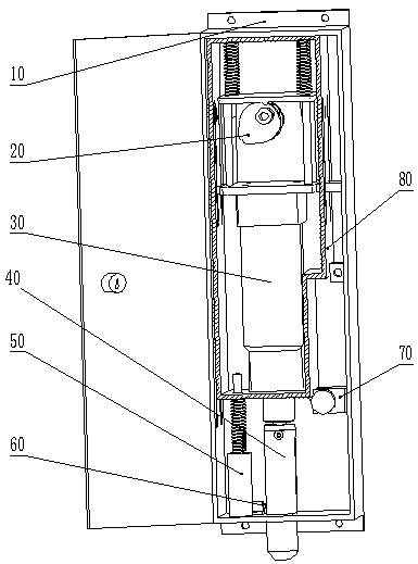
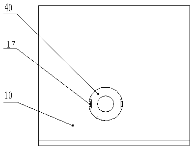
The invention relates to the technical field of access control, in particular to an automatic bolt lock for a side hung door and the side hung door. The automatic bolt lock for the side hung door comprises an outer shell, an inner shell, a push rod motor and a bolt, a guide rod extends downwards from the top surface of the outer shell, a limiting support rod extends upwards from the bottom surfaceof the outer shell, the limiting support rod is used for supporting the inner shell, and a through hole I for penetrating of the bolt is formed in the bottom surface. The inner shell is arranged between the limiting support rod and the top surface of the outer shell, the push rod motor is located in the inner shell, a plate-shaped member is fixed on a base of the push rod motor, a push rod of thepush rod motor extends out of the bottom surface of the inner shell and is connected with the bolt, the end of the guide rod sequentially penetrates through a through hole II formed in the top surface of the inner shell and a through hole III formed in the plate-shaped member, and the portion, between the plate-shaped member and the top surface of the inner shell, of the guide rod is sleeved withan elastic member I. The automatic bolt lock has the following advantages that the problem that the motor is blocked easily when the bolt is blocked in the releasing process is solved; the bolt can be prevented from being pried and unlocked by external force, and the door body can be prevented from deforming under the action of gravity.

Description

technical field [0001] The invention relates to the technical field of access control, in particular to an automatic latch lock for a swing door and a swing door. Background technique [0002] Swing doors are the most common way to open doors in current life. The principle is to hinge the door body on the door post so that the door body can rotate around the door post, and then provide driving force through the door opener to open and close the door. It can be seen from its principle that one end of the swing door is in a free state similar to the cantilever structure and is easy to be pushed. In order to limit the free state of the end of the swing door, a latch lock is generally installed at the bottom of the end of the swing door. When the door is closed, the latch Insert into the base hole, or directly into the ground to lock the door. This solution can only limit the movement of the end of the swing door, and every time the door is opened and closed, manual operation i...

Claims


Application Information

Patent Timeline
Patent Type & Authority Applications(China)
IPC IPC(8): E05B63/08E05B47/00E05B17/20
CPCE05B63/08E05B47/0001E05B17/2084
Inventor 刘润根
Owner JIANGXI BAISHENG GATE & DOOR AUTOMATION
Learn More