Gas spray tube of gas water heater

A technology for gas water heaters and jet pipes, which is applied in the direction of burners, fluid heaters, gas fuel burners, etc. It can solve the problems of sealing, inability to achieve large flow, and small air intake passages, so as to achieve good sealing effect and improve the efficiency of air intake. The effect of injecting air once and reducing harmful gases

Pending Publication Date: 2019-09-06
GUANGDONG VANWARD NEW ELECTRIC CO LTD
View PDF0 Cites 2 Cited by
  • Summary
  • Abstract
  • Description
  • Claims
  • Application Information

AI Technical Summary

Problems solved by technology

[0006] Because the existing air jet pipe is tubular, the air intake channel is small, and it cannot achieve a large flow rate. The volume of the normally open air intake chamber and the first gas distribution air intake chamber is large, which is conducive to achieving a large flow rate, but it cannot pass through the existing air intake chamber. The molding process is one-time molding, and the opening must be set, and the opening needs to be sealed

Method used


Image

  • Gas spray tube of gas water heater
  • Gas spray tube of gas water heater
  • Gas spray tube of gas water heater

Examples


Embodiment 1

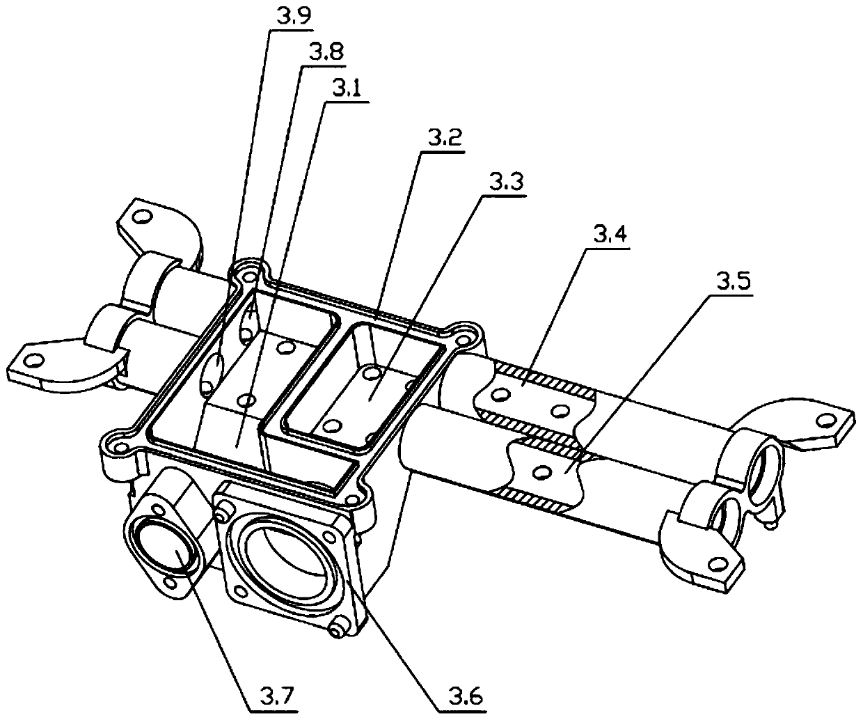
[0030] Such as figure 1 , 2 As shown, a gas injection pipe of a gas water heater includes a gas injection pipe main body 3, a first shut-off valve 4 arranged on the side of the air injection pipe main body 3, and a nozzle 5 arranged in the air injection pipe main body 3, wherein the gas injection pipe of a gas water heater It also includes a cover plate 1, a sealing member 2, and a plug 6. The plug 6 is fixed on the end of the jet pipe main body 3, and the cover plate 1 is fixed to the jet pipe main body 3 through the sealing member 2.

[0031] In this embodiment, the cover plate 1 and the sealing member 2 are added, and the internal structure of the jet pipe main body 3 can achieve a large flow rate, can improve the amount of air injected once, and then reduce the harmful gases (CO, NO) after combustion of the gas. X ).

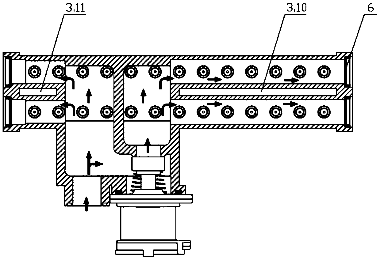
[0032] Such as figure 2 , 3 Among them, the inner cavity of the jet pipe main body 3 is provided with an air inlet channel, a first air distribution ch...

Embodiment 2

[0047] Such as Figure 4 As shown, in this embodiment, on the basis of Embodiment 1, a second cut-off valve 7 is additionally provided; the second gas distribution inlet cavity 3.12, the fifth gas distribution channel 3.13, and the sixth gas distribution channel are also added on the main body of the jet pipe. 3.14. The second cut-off valve installation platform 3.15; the fifth gas distribution channel 3.13 and the sixth gas distribution channel 3.14 are independent of each other and communicate with the second gas distribution inlet chamber 3.12; the second gas distribution inlet chamber 3.12 is connected to the normal inlet The air cavity 3.1 is connected through a valve; the second stop valve 7 is installed on the second stop valve installation platform 3.15, and controls the on-off of the valve; The channel 3.16 runs through the fifth gas distribution channel 3.13 and the sixth gas distribution channel 3.14.

[0048] The working principle of this embodiment:

[0049] Dur...


PUM


Abstract

The invention relates to the technical field of water heaters, in particular to a gas spray tube of a gas water heater. The gas spray tube of the gas water heater comprises a gas spray tube main body,a first stop valve arranged on the side part of the gas spray tube main body, and a spray nozzle arranged in the gas spray tube main body, and further comprises a cover plate, a sealing part and a choke plug, wherein the choke plug is fixedly arranged on the end part of the tube body of the gas spray tube main body, and the cover plate is fixed to the gas spray tube main body through the sealingpart. The gas spray tube can achieve great flow, and can increase injection once air amount, so that harmful gases (CO and NOX) after gas is combusted are reduced.

Description

technical field [0001] The present invention relates to the technical field of water heaters, and more specifically, to an air injection pipe of a gas water heater. Background technique [0002] People's awareness of environmental protection is increasing. The combustion of gas water heaters will inevitably produce waste gas. The harmful gases in the waste gas are mainly CO and NO. X , the root cause of these harmful gases is whether the amount of primary air entering the burner can achieve as complete combustion as possible. The structure of the burner assembly determines the amount of primary air, and the jet pipe is one of the main components of the burner assembly and plays a vital role. [0003] In the prior art, part of the gas injection pipe of the gas water heater is tubular, and the air intake channel is small, so a large flow rate cannot be achieved. In the prior art, the gas injection pipe is usually provided with a row of nozzles, resulting in less primary air ...

Claims


Application Information

Patent Timeline
Patent Type & Authority Applications(China)
IPC IPC(8): F23D14/04F23D14/48F24H9/18
CPCF23D14/04F23D14/48F24H9/1836
Inventor 卢宇凡周奋何意
Owner GUANGDONG VANWARD NEW ELECTRIC CO LTD
Why Eureka
Try Eureka