
Knob switch

A rotary switch and knob technology, applied in electric switches, electrical components, circuits, etc., can solve the problems of large installation space, easy fatigue of elastic parts, easy wear of track surface, etc., achieve convenient installation, improve control accuracy, and small installation space Effect

Pending Publication Date: 2019-09-13
KOSTAL SHANGHAI ELECTROMECHANICAL CO LTD +1
View PDF0 Cites 2 Cited by
  • Summary
  • Abstract
  • Description
  • Claims
  • Application Information

AI Technical Summary

Problems solved by technology

[0004] However, in actual use, the elastic member is compressed when the rotary switch is rotated from one gear position to another, so after long-term use, the track surface is easy to wear, and the elastic member is also prone to fatigue, which leads to gear failure. The position pin shakes, which affects the positioning effect of the position pin and reduces the control accuracy of the knob switch
In addition, the elastic part needs to have a certain deformation during the assembly process in order to ensure the resisting effect on the positioning pin, so the assembly process is more complicated
And the knob switch needs to reserve a certain space for the deformation of the elastic part, so the installation space required is larger

Method used


Image

  • Knob switch
  • Knob switch
  • Knob switch

Examples


Embodiment Construction

[0030] The following will clearly and completely describe the technical solutions in the embodiments of the present invention with reference to the accompanying drawings in the embodiments of the present invention. Obviously, the described embodiments are only some, not all, embodiments of the present invention. Based on the embodiments of the present invention, all other embodiments obtained by persons of ordinary skill in the art without making creative efforts belong to the protection scope of the present invention.

[0031] The core of the present invention is to provide a rotary switch with high control precision, convenient installation and small required installation space.

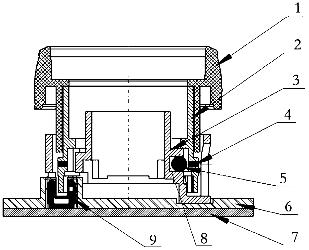
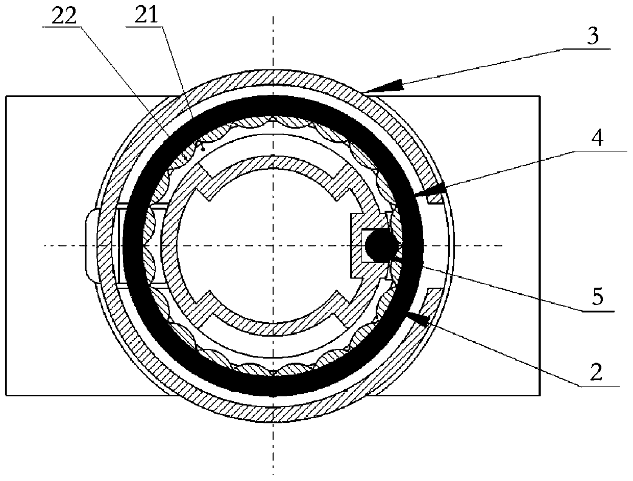
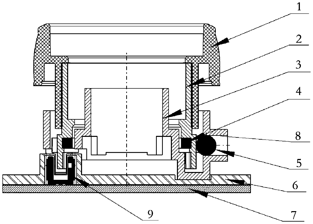
[0032] Please refer to Figure 1~6 , figure 1 and figure 2 Respectively, the front view and the top view of the first rotary switch provided by the present invention; image 3 and Figure 4 Respectively, the front view and the top view of the second rotary switch provided by the present invent...


PUM


Abstract

The invention discloses a knob switch. The knob switch comprises a first magnetic body, a second magnetic body, a fixed support and a knob body capable of rotating relative to the fixed support, wherein one of the fixed support and the knob body is provided with a gear locking part, and the other one of the fixed support and the knob body is provided with the first magnetic body; the first magnetic body and the second magnetic body are oppositely distributed, magnetically connected and distributed on two sides of the gear locking part, and the first magnetic body is abutted against the gear locking part so as to fix the knob body on a target gear. The rotary switch provided by the invention optimizes the precision of the operation hand feeling and the long-term use stability on the basis of simplifying of the part structure, reduction of the number of parts, reduction of the demand to the assembling space and reduction of the assembling difficulty.

Description

technical field [0001] The invention relates to the technical field of automotive interior appliances, in particular to a rotary switch. Background technique [0002] At present, most of the interior appliances or control modules of automobiles are provided with knob switches to realize the adjustment processes such as temperature adjustment of air-conditioning equipment and volume adjustment of entertainment equipment. [0003] The interior of the knob switch realizes rotation or toggle control through a mechanical contact structure. The knob is provided with a track surface and a fixed part that can rotate relative to the track surface. There is a gear pin between them, and a shrapnel or spring is set at one end of the gear pin. The other end of the elastic member is against the track surface, and the gear pin is in force contact with the track surface under the action of the elastic member. When the knob rotates, it forms a relative force movement with the track surface t...

Claims


Application Information

Patent Timeline
Patent Type & Authority Applications(China)
IPC IPC(8): H01H19/14H01H19/02
CPCH01H19/14H01H19/02
Inventor 张洪铭孙浩然
Owner KOSTAL SHANGHAI ELECTROMECHANICAL CO LTD
Learn More