Full-hydraulic humanoid manipulator

A humanoid, manipulator technology, applied in the field of manipulators, can solve the problems of difficulty in precise adjustment, the product cannot have a good clamping effect, and the control movement accuracy is not enough.

Active Publication Date: 2019-09-20
TIANHE COLLEGE GUANGDONG POLYTECHNIC NORMAL UNIV
9 Cites 0 Cited by

AI-Extracted Technical Summary

Problems solved by technology

[0002] A manipulator is an automatic operating device that can imitate certain movements and functions of the human hand and arm to grab, carry objects or operate tools according to a fixed program. At present, industrial robots and service robots require different end effectors, and the manipulator claw is one of them. In order to meet the needs of different applications, different end effectors have been designed, including the claw type; at present, the claw type end effector is often only a simple double-joint structure, which is not available for finer and more complex products. Good clamping effect, and the control motion precision is ...

Method used

[0030] The oil flow channel 5011 and the valve body moving channel 5013 are provided with a pincer channel 5012, and the width of the...

Abstract

The invention provides a full-hydraulic humanoid manipulator which comprises a control module and a gripper module. The full-hydraulic humanoid manipulator is characterized in that the control module comprises a control motor, a threaded shaft, a bearing, a valve, a valve body and a pipe joint; the control motor is connected with the threaded shaft; a bearing is arranged between the threaded shaft and the valve; the valve is fixedly arranged at the other end of the threaded shaft and is arranged in the valve body; the pipe joint is arranged under the valve body; through a precise liquid flow control device, a finger knuckle liquid flow can be controlled, so that the requirement on adjusting each finger according to the needs can be met; and fingers are driven through a precise special micro oil cylinder and are automatically controlled through a computer, so that opening, closing and grasping of any finger at different degrees can be realized. The strength magnitude can be adjusted through a control pressure valve according to the feedback.

Application Domain

Gripping heads

Technology Topic

Automatic controlManipulator +2

Image

  • Full-hydraulic humanoid manipulator
  • Full-hydraulic humanoid manipulator
  • Full-hydraulic humanoid manipulator

Examples

  • Experimental program(2)

Example Embodiment

[0034] Example 1:
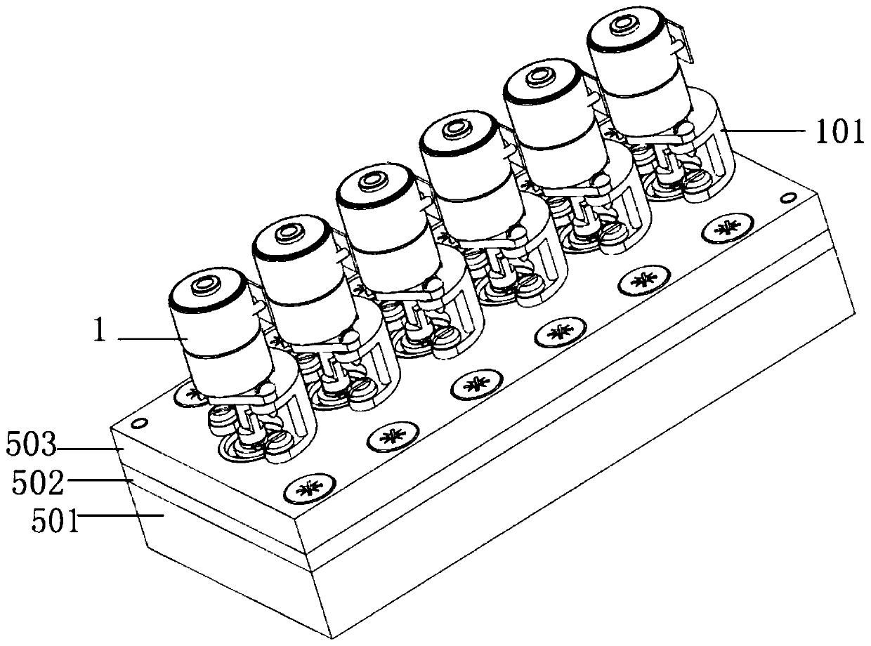
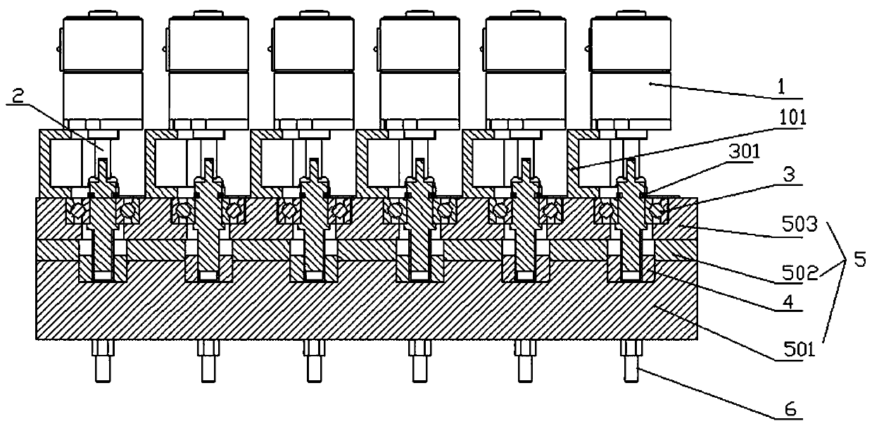
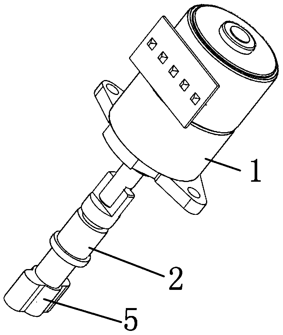
[0035] The manipulator is set as figure 2 The two-finger structure shown. The control motor 1 is controlled by the program instructions and can perform macro single-step or continuous rotation, and drive the threaded shaft 2 to rotate. The threaded shaft 2 and the valve 4 are connected by precision fine thread, because the threaded shaft 2 and the bearing 3 that cannot move up and down Fixed connection, therefore, when the threaded shaft 2 rotates, it drives the valve 4 to move up and down, thereby controlling the opening and closing degree of the valve 4 to achieve the purpose of controlling the flow rate of the liquid flow; at the same time, a clamp channel 5012 is set in the flow channel. The width of the flow channel is preferably set to 1mm. The liquid flow comes to the oil pipe through the connection port-the conduit-the first oil connection port. When the liquid flow enters the first oil port 803 and exits the second oil port 804, the piston 801 is pushed to move downward , Produce mechanical finger grasping action; on the contrary, when the liquid flow comes out from the first oil port 803 and the second oil port 804 enters, it will produce the action of spreading the fingers, and the change of the oil port liquid flow direction can be electrically controlled by the reversing valve.

Example Embodiment

[0036] Example 2:
[0037] The manipulator has a three-finger structure. It can be set to have two fingers on one side and one finger on the other side, or it can be set with three fingers distributed in a triangle. The control motor 1 is controlled by program instructions, and it can perform macro single step or continuous rotation, and drive the threaded shaft 2 to rotate. 2 The axis and the valve 4 are connected with precision fine threads. Because the threaded shaft 2 is fixedly connected to the bearing 3 that cannot move up and down, when the threaded shaft 2 rotates, it drives the valve 4 to move up and down, thereby controlling the opening and closing of the valve 4. To achieve the purpose of controlling the size of the liquid flow; at the same time, a clamp flow channel 5012 is set in the flow channel. The width of the flow channel is preferably set to 0.8mm. The liquid flow comes to the tubing through the nozzle-pipe-first oil-receiving port, When the liquid flow enters from the first oil port 803 and the second oil port 804 exits, the piston 801 is pushed to move downward, causing the gripping action of the mechanical fingers; on the contrary, the liquid flow comes out of the first oil port 803 and the second oil port 804 When it enters, it produces the action of spreading the finger, and the change of the flow direction of the oil port can be electrically controlled by the reversing valve.

PUM

no PUM

Description & Claims & Application Information

We can also present the details of the Description, Claims and Application information to help users get a comprehensive understanding of the technical details of the patent, such as background art, summary of invention, brief description of drawings, description of embodiments, and other original content. On the other hand, users can also determine the specific scope of protection of the technology through the list of claims; as well as understand the changes in the life cycle of the technology with the presentation of the patent timeline. Login to view more.
Why Eureka
Try Eureka