
Electrical control cabinet with heat dissipation function

A technology for electrical control cabinets and electrical cabinets, which is applied to electrical components, substation/distribution device enclosures, substation/switch layout details, etc.

Inactive Publication Date: 2019-09-20
TAICANG DENASEN MECHANICAL & ELECTRICAL ENG CO LTD
View PDF0 Cites 1 Cited by
  • Summary
  • Abstract
  • Description
  • Claims
  • Application Information

AI Technical Summary

Problems solved by technology

[0004] The purpose of the present invention is to provide an electrical control cabinet with heat dissipation function to solve the problem that the internal components of the electrical cabinet proposed in the above background technology will emit a certain amount of heat when working, and most of the cabinets themselves use grids for heat dissipation. Its effect is not significant enough, and the problem of dust accumulation is easy to occur inside

Method used


Image

  • Electrical control cabinet with heat dissipation function
  • Electrical control cabinet with heat dissipation function
  • Electrical control cabinet with heat dissipation function

Examples


Embodiment Construction

[0019] The following will clearly and completely describe the technical solutions in the embodiments of the present invention with reference to the accompanying drawings in the embodiments of the present invention. Obviously, the described embodiments are only some, not all, embodiments of the present invention.

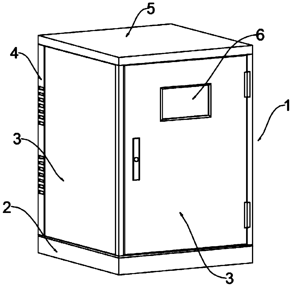
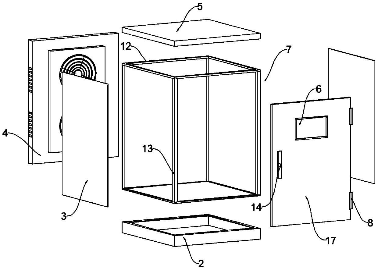
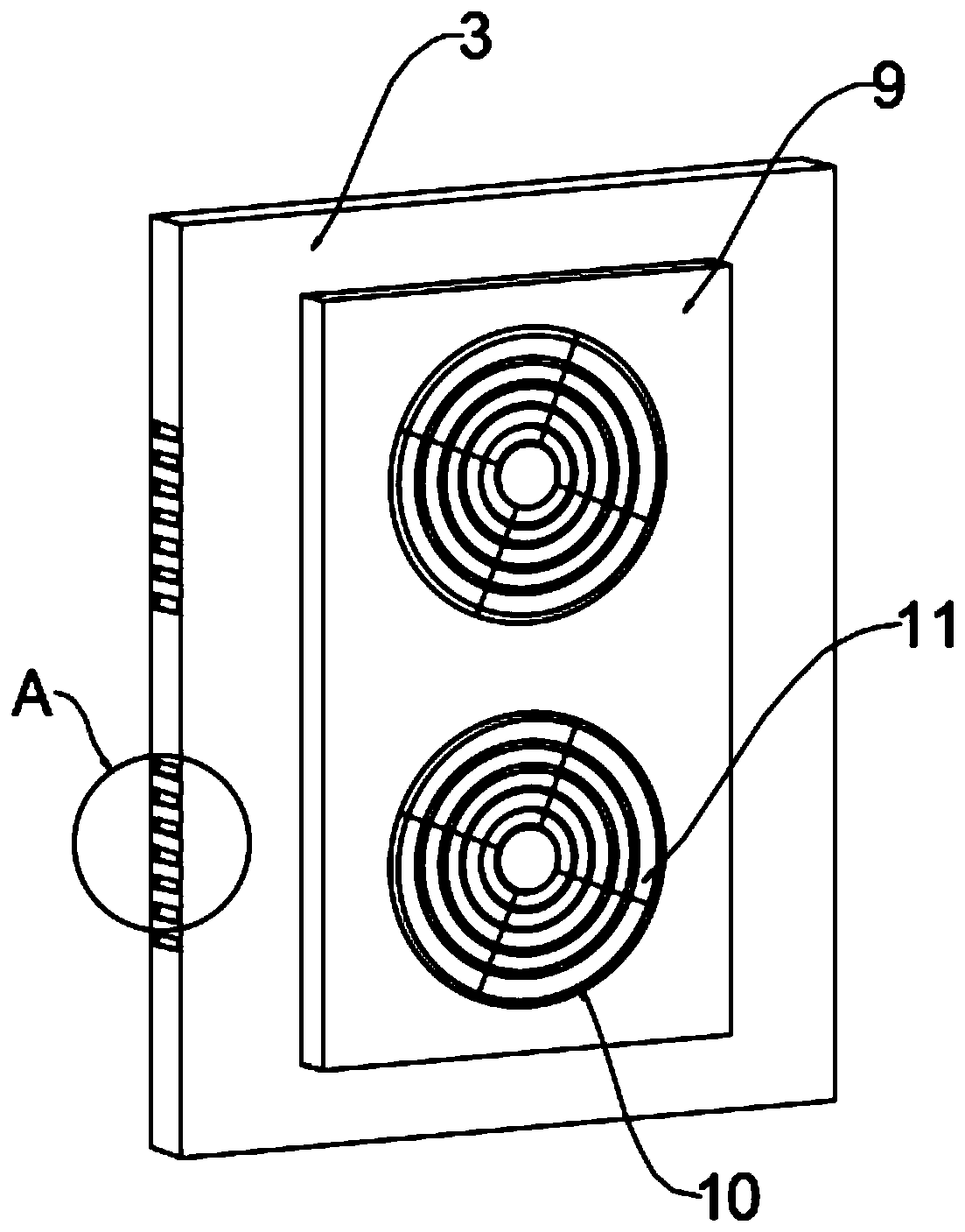
[0020] see Figure 1-4 , an embodiment provided by the present invention: an electrical control cabinet with heat dissipation function, including an assembled heat dissipation electric cabinet 1, the bottom of the assembled heat dissipation electric cabinet 1 is provided with a wiring base 2, and the circuit can be connected to the cabinet body from the base Among them, a metal cabinet door 17 is arranged on the top of the wiring base 2, a glass observation window 6 is arranged on the outer surface of the metal cabinet door 17, and a protective lock 14 is arranged under the glass observation window 6. The upper and lower sides of the metal cabinet door 17 are A metal...


PUM


Abstract

The invention discloses an electrical control cabinet with a heat dissipation function, relates to the technical field of an electrical control cabinet and is to solve the problem that since inner components of an electrical cabinet give off a certain amount of heat during working, but most of the cabinets adopt grid type heat dissipation, so that the effect is not obvious, and the inner portion of the cabinet is easy to accumulate dust in the prior art. The bottom portion of an assemble heat dissipation electric cabinet is provided with a wiring base; a metal cabinet door is arranged above the wiring base; the outer surface of the metal cabinet door is provided with a glass observation window; a protection lock is arranged under the glass observation window; the upper and lower two ends of one side of the metal cabinet door are respectively provided with a metal hinge; the other side of the metal cabinet door is provided with a support skeleton; the two sides of the support skeleton are respectively provided with a cabinet side seal plate; a cabinet cover plate is arranged above the support skeleton; and one side of the cabinet cover plate is provided with a cabinet back plate.

Description

technical field [0001] The invention relates to the technical field of electric control cabinets, in particular to an electric control cabinet with heat dissipation function. Background technique [0002] The control cabinet is to assemble the switchgear, measuring instrument, protective device and auxiliary equipment in the closed or semiclosed metal cabinet or on the screen width according to the requirements of electrical wiring. and the safety of surrounding equipment. During normal operation, the circuit can be connected or disconnected by means of a manual or automatic switch. Cut off the circuit or alarm with the help of protective electrical appliances in case of failure or abnormal operation. Various parameters in operation can be displayed by means of measuring instruments, and some electrical parameters can also be adjusted to prompt or send out signals for deviations from normal working conditions. Commonly used in various power generation, distribution and su...

Claims


Application Information

Patent Timeline
IPC IPC(8): H02B1/56H02B1/30H02B1/28
CPCH02B1/28H02B1/306H02B1/565
Inventor 倪晔波
Owner TAICANG DENASEN MECHANICAL & ELECTRICAL ENG CO LTD
Learn More