Expanded heat dissipation power distribution cabinet

A power distribution cabinet and unfolded technology, applied in substation/power distribution device housing, electrical components, substation/switch layout details, etc., can solve the problems of non-adjustable heat dissipation function, poor heat dissipation performance, equipment impact, etc., and achieve heat dissipation effect Good, prevent temperature rise and accelerate air flow

Pending Publication Date: 2021-01-05
ANHUI WANKONG SET EQUIP MFG
View PDF5 Cites 0 Cited by
  • Summary
  • Abstract
  • Description
  • Claims
  • Application Information

AI Technical Summary

Problems solved by technology

However, because the current box-type substation is in a closed box environment, its heat dissipation performance is poor, and the heat dissipation function is not adjustable, which has poor adaptability to extreme weather conditions or seasonal changes, and will have a certain impact on internal equipment.

Method used


Image

  • Expanded heat dissipation power distribution cabinet
  • Expanded heat dissipation power distribution cabinet
  • Expanded heat dissipation power distribution cabinet

Examples


Embodiment 1

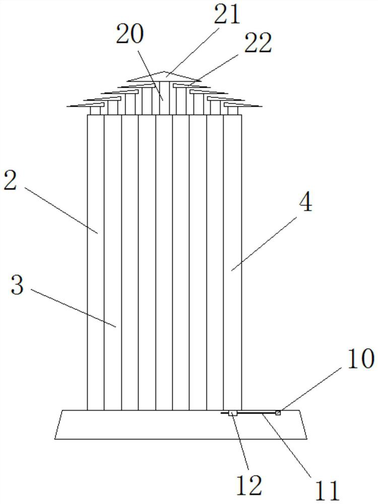
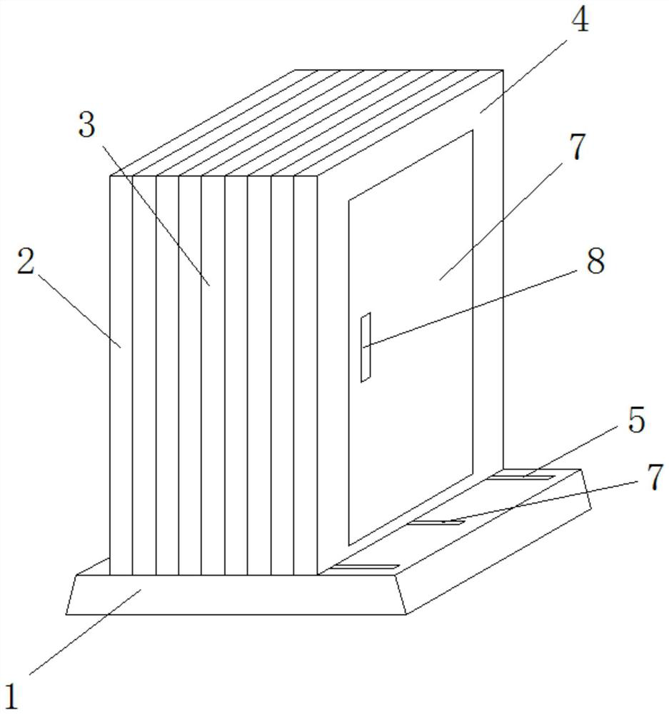
[0021] Embodiment 1: as Figure 1-6 As shown, an unfolded heat dissipation power distribution cabinet includes a base 1, a tail plate 2 is fixedly installed on the top left side of the base 1, and a plurality of frames 3 are movably connected to the top side of the middle part of the base 1, The right part of described base 1 offers limit groove 7, and the right end of described limit groove 7 is fixedly installed with first motor 10, and the left end of described first motor 10 is fixedly connected with screw mandrel 11, and described screw mandrel 11 A moving block 12 is connected to the top by a screw thread, and the moving block 12 is movably clamped with the limit groove 7. The top of the moving block 12 is fixedly connected with the front plate 4, the front plate 4, the tail plate 2 and several frames 3 can form a box;

[0022] The inner walls on both sides of the front plate 4, the tail plate 2, and several frames 3 are rotatably connected with casings 13, and connecti...

Embodiment 2

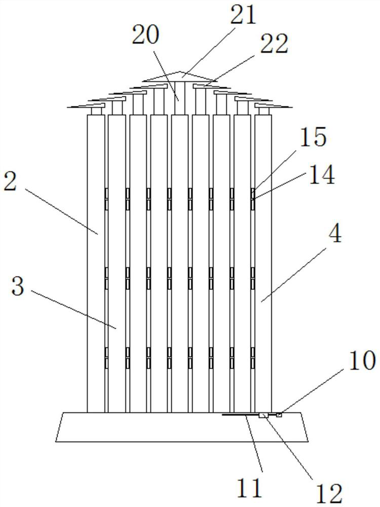
[0028] Embodiment 2: as Figure 1-6 As shown, an unfolded heat dissipation power distribution cabinet includes a base 1, a tail plate 2 is fixedly installed on the top left side of the base 1, and a plurality of frames 3 are movably connected to the top side of the middle part of the base 1, The right part of described base 1 offers limit groove 7, and the right end of described limit groove 7 is fixedly installed with first motor 10, and the left end of described first motor 10 is fixedly connected with screw mandrel 11, and described screw mandrel 11 A moving block 12 is connected to the top by a screw thread, and the moving block 12 is movably clamped with the limit groove 7. The top of the moving block 12 is fixedly connected with the front plate 4, the front plate 4, the tail plate 2 and several frames 3 can form a box;

[0029] The inner walls on both sides of the front plate 4, the tail plate 2, and several frames 3 are rotatably connected with casings 13, and connecti...


PUM


Abstract

The invention discloses an expanded heat dissipation power distribution cabinet which comprises a base, a tail plate is fixedly installed on the top side of the left portion of the base, a plurality of frames are movably connected to the top side of the middle of the base, a limiting groove is formed in the right portion of the base, and a first motor is fixedly installed at the right end of the limiting groove. A lead screw is fixedly connected to the left end of the first motor, a movable block is spirally connected to the lead screw through a thread, the movable block is movably connected with the limiting groove in a clamped mode, a front plate is fixedly connected to the top of the movable block, and the front plate, the tail plate and the multiple frames can form a box body. Sleevesare rotatably connected to the inner walls of the two sides of the front plate, the tail plate and the multiple frames, a connecting rod is movably connected between every two adjacent sleeves, and blades are fixedly connected to the middles of the connecting rods. The heat dissipation device is simple in structure, convenient to use, practical, good in heat dissipation effect and capable of preventing electrical elements from breaking down due to temperature rise.

Description

Technical field: [0001] The invention relates to the field of power distribution cabinets, in particular to an unfolded heat dissipation power distribution cabinet. Background technique: [0002] The power distribution cabinet (box) is divided into power distribution cabinet (box), lighting distribution cabinet (box), metering cabinet (box), and is the final equipment of the power distribution system. The power distribution cabinet is a general term for the motor control center. The power distribution cabinet is used in the occasions where the load is relatively scattered and there are few circuits; the motor control center is used in the occasions where the load is concentrated and there are many circuits. They distribute the electric energy of a certain circuit of the upper-level power distribution equipment to the nearest load. This level of equipment shall provide protection, monitoring and control of the load; [0003] With the development and progress of the power i...

Claims


Application Information

Patent Timeline
Patent Type & Authority Applications(China)
IPC IPC(8): H02B1/30H02B1/56H02B1/28
CPCH02B1/30H02B1/565H02B1/28
Inventor 章恒玓
Owner ANHUI WANKONG SET EQUIP MFG
Why Eureka
Try Eureka