A surface defect detection method, terminal equipment and storage medium

A defect detection and defect technology, applied in image analysis, image enhancement, instruments, etc., can solve problems such as inability to achieve defect contour segmentation, inappropriate detection objects and defect types, and raising the threshold for monitoring system development.

Active Publication Date: 2021-08-20
XIAMEN UNIV
View PDF7 Cites 0 Cited by
  • Summary
  • Abstract
  • Description
  • Claims
  • Application Information

AI Technical Summary

Problems solved by technology

[0004] 1) The processing process is complex, and the defect determination process requires manual design of features, which raises the threshold for monitoring system development;
[0005] 2) The generalization ability of manually designed defect features is poor, and it is not suitable for new detection objects and defect types;
[0006] 3) Limited to defect location and classification, it is temporarily impossible to segment defect contours, which makes it impossible to achieve effective negative feedback in the manufacturing process to adjust production parameters

Method used


Image

  • A surface defect detection method, terminal equipment and storage medium
  • A surface defect detection method, terminal equipment and storage medium
  • A surface defect detection method, terminal equipment and storage medium

Examples


Embodiment 1

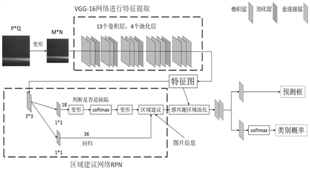
[0057] The present invention provides a surface defect detection method, which is implemented based on the improved Faster R-CNN network. This embodiment uses the surface defect detection just now as an example to illustrate. In other embodiments, this method can also be applied to other items in the detection of surface defects.

[0058] The method described in this embodiment comprises the following steps:

[0059] Step 1: Collect defect images on the steel surface to form a training set, and label the defect images in the training set, and the labels include defect types and defect location frames.

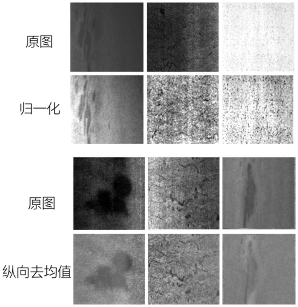
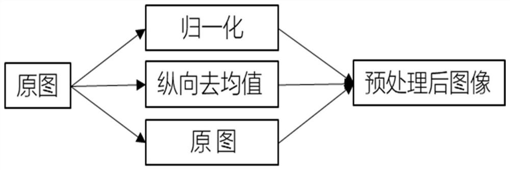
[0060] Furthermore, because the collected defect images not only have obvious light and dark differences globally, but also have huge differences in left and right lighting. Therefore, this embodiment also includes preprocessing the collected defect images. Specifically, two image processing methods are mainly used on the initial image:

[0061] The first one is to normalize...

Embodiment 2

[0172] The present invention also provides a surface defect detection terminal device, including a memory, a processor, and a computer program stored in the memory and operable on the processor, and the present invention is realized when the processor executes the computer program Steps in the above method embodiment of Embodiment 1.


PUM


Abstract

The present invention relates to a surface defect detection method, terminal equipment and storage medium. The method includes: S1: collecting defect images of detection objects to form a training set, and marking the defect images in the training set; S2: constructing defect images The detection model is trained by inputting the training set into the defect detection model to obtain the trained defect detection model; the defect detection model is constructed based on the Faster R-CNN network, and its feature extraction network is a VGG-16 network, and the VGG-16 network , superimpose the output of the third layer and the output of the fifth layer; S3: Input the defect image to be detected into the trained defect detection model, and obtain the defect location frame and defect type in the defect image; S4: According to the defect image to be detected The defect localization frame in the defect image is used to segment the defect. The invention is based on the Faster R-CNN network and the threshold segmentation method, so that the defect type, position and outline can be output only by inputting an image during the detection process, that is, the end-to-end detection of defects is realized.

Description

technical field [0001] The present invention relates to the technical field of image detection, in particular to a surface defect detection method, a terminal device and a storage medium. Background technique [0002] Not only are there many types of steel surface defects, but the distribution is not fixed. A steel surface image to be inspected may have multiple types of defects; in addition, the problem of uneven illumination during image acquisition will interfere with the machine inspection process. Therefore, traditional production enterprises are still at the stage of manual steel surface inspection. In the production process of hot-rolled strip steel, because the production temperature is as high as hundreds of degrees Celsius, manual quality inspection can only be carried out at the end of the coil. The method of random inspection after production is not only unable to achieve effective control of the cause of defects, but also makes quality objections frequently occ...

Claims


Application Information

Patent Timeline
Patent Type & Authority Patents(China)
IPC IPC(8): G06T7/00G06T7/11G06T7/136
CPCG06T7/0004G06T2207/20081G06T2207/20084G06T2207/30136G06T7/11G06T7/136
Inventor 邵桂芳高凤强李铁军刘暾东徐珊波陈聿文
Owner XIAMEN UNIV
Why Eureka
Try Eureka