[0018] In order to enable those skilled in the art to better understand the solutions of the present application, the technical solutions in the embodiments of the present application will be described clearly and completely in conjunction with the accompanying drawings in the embodiments of the present application.
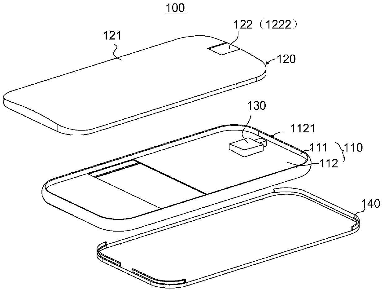
[0019] With the rapid improvement of the performance of mobile terminals, users have higher and higher requirements for the functions of the mobile terminals, especially in terms of shooting performance. In order to satisfy users who can use the mobile terminal for panoramic shooting or large-angle shooting, the mobile terminal is usually equipped with at least one wide-angle lens. Since the front lens of the wide-angle lens is usually spherical, its lens surface is convex relative to the mobile terminal housing, so it is easy to wear . Therefore, it is usually necessary to install a protective glass outside the wide-angle lens of the mobile terminal to protect the wide-angle glass from abrasion. However, the setting of the protective glass will block the wide-angle lens, which will affect the viewing angle of the wide-angle lens, and thus cannot obtain a larger shooting angle, resulting in large The effect of angle or panorama shooting is poor.
[0020] The inventor found that if a wide-angle lens needs to be used for large-angle shooting, extending the wide-angle lens out of the mobile terminal can prevent the wide-angle lens from being blocked, thereby obtaining a larger viewing angle for shooting. If it is not necessary to use a wide-angle lens, retract the wide-angle lens to the mobile terminal to avoid wear of the wide-angle lens.
[0021] Therefore, the inventor proposes the mobile terminal provided by the embodiment of the present application.
[0022] Please refer to figure 1 , An embodiment of the present application provides a mobile terminal 100, which may include: a middle frame 110, a lens module 130, and a back cover 120, wherein the lens module 130 is disposed on the middle frame 110, and the back cover 120 is assembled on The middle frame 110 is located on one side of the lens module 130 and is used to protect the lens module 130 and serve as the exterior surface of the mobile terminal 100.
[0023] It should be noted that the mobile terminal 100 of this embodiment may be an electronic device with a photographing function, such as a smart phone or a tablet computer.
[0024] See again figure 1 The middle frame 110 includes a middle plate 111 and a frame 112. The frame 112 is connected to the edge of the middle plate 111 and is arranged around the middle plate 111; the frame 112 is provided with a through hole 1121. The wide-angle lens in the lens module 130 can extend out of the frame 112 through the through hole 1121 or retract into the middle frame 110. The front shell 140 and the back cover 120 can be installed on opposite sides of the middle frame 110, respectively. The middle plate 111 can be used to install various components of the mobile terminal 100, and the frame 112 can usually be used to set the switch button, Microphone, speakers, etc.
[0025] In some embodiments, the lens module 130 may be installed on one or both sides of the middle plate 111, for example, it may be installed between the middle plate 111 and the front housing 140, or may be installed between the middle plate 111 and the rear cover 120. It can also be installed between the middle plate 111 and the front shell 140 and between the middle plate 111 and the rear cover 120 at the same time. Correspondingly, the through hole 1121 opened by the frame 112 can be located between the middle plate 111 and the front shell 140, or between the middle plate 111 and the rear cover 120, and can also be located between the middle plate 111 and the front shell 140 at the same time. Between the plate 111 and the back cover 120. Optionally, the cross-section of the through hole 1121 may be rectangular, circular, or various special-shaped cross-sections.
[0026] Optionally, the through hole 1121 can be arranged at any position of the frame 112. For example, a switch button is installed on one side of the frame 112, and the through hole 1121 can be arranged on the side of the frame 112 where the switch button is installed, or can be arranged at The frame 112 is opposite to the side where the switch button is installed, and can also be arranged on the side adjacent to the frame 112 and the side where the switch button is installed.
[0027] In some embodiments, the through hole 1121 may be provided on the side of the frame where the sound-receiving port is provided.
[0028] Please refer to figure 2 The lens module 130 includes a wide-angle lens 131 and a telescopic component 134. The telescopic component 134 is disposed in the middle frame 110 and connected with the wide-angle lens 131 to selectively drive the wide-angle lens 131 to extend or retract along the axis of the through hole 1121. In the box 110.
[0029] In practical applications, if the wide-angle lens 131 needs to be used for large-angle shooting, the wide-angle lens 131 can be driven by the telescopic assembly 134 to extend the frame 112 along the axis of the through hole 1121 for shooting, that is, extend the housing of the mobile terminal 100. At this time, since the wide-angle lens 131 is not blocked by components of the mobile terminal 100, such as the housing and the back cover 120, the wide-angle lens 131 can obtain a larger viewing angle for shooting, which is beneficial to taking panoramic pictures or pictures with a larger viewing angle. . Since the front lens of the wide-angle lens 131 is spherical and the surface is convex, it is more susceptible to wear than a flat lens. Therefore, when the wide-angle lens 131 is not needed for large-angle shooting, the wide-angle lens 131 can be driven along the through hole 1121 through the telescopic assembly 134 Retracts into the middle frame 110 in the axial direction, that is, retracts into the housing of the mobile terminal 100, so that the housing of the mobile terminal 100 can protect the wide-angle lens 131 and prevent the wide-angle lens 131 from being worn. Among them, the telescopic component 134 can be a spring, an electromagnet, a stepper motor, a linear motor, and the like.
[0030] In some embodiments, see image 3 The wide-angle lens 131 includes a lens body 1311 and a lens body 1312. The lens body 1312 is connected to the lens body 1311 for light transmission. The lens body 1312 is, for example, roughly hemispherical and made of transparent materials. The lens body 1312 includes a first part 1313 and a second part 1314. The second part 1314 surrounds the first part 1313 and is connected to the first part 1313. The first part 1313 means that the light entering the lens body 1312 can be roughly aligned with the optical axis of the wide-angle lens 131. The parallel part, the second part 1314 may refer to the part of the lens body 1312 excluding the first part 1313, or the part where the light entering the lens body 1312 and the optical axis of the wide-angle lens 131 form a larger angle. For example, such as image 3 As shown, in the front projection formed by the lens body 1312 on the plane where the lens body is located, the projection of the first part 1313 forms a circle with the projection of the lens body 1312 as the center and a radius R1, wherein the radius R1 is less than or equal to the radius of the lens body 1/2 of R2. The radius of the radius R2 of the lens body refers to the radius of the circle formed by the projection of the lens body 1312 on the lens body. It can be understood that the lens body refers to the part of the lens body used to encapsulate the lens body in the wide-angle lens.
[0031] In other embodiments, the lens module 130 may further include a cover plate 150 for closing the through hole 1121 when the wide-angle lens 131 is retracted into the middle frame 110. In some embodiments, the cover 150 may be connected to the wide-angle lens 131 and move with the wide-angle lens 131 to expand and contract. By setting the cover 150 to close the through hole 1121 when the wide-angle lens 131 is retracted into the middle frame 110, it can protect the wide-angle lens 131 when not in use, and also prevent dust from entering the mobile terminal 100.
[0032] In some embodiments, see Figure 5 The cover 150 may also be arranged on the edge of the frame at the through hole. At this time, the lens module 130 may also include a reset member 160. The cover 150 and the edge of the frame 112 at the through hole 1121 are hinged to The cover 150 can be opened when the lens module extends out of the frame. The reset member 160 is used to reset the cover 150, so that when the lens module is retracted into the middle frame, the cover 150 can automatically reset and close the through hole. As an example, the reset member 160 may be a reset torsion spring, and the reset spring may be directly sleeved on the pivot between the cover 150 and the frame 112 and resist the cover 150. The cover 150 is reset by setting the resetting member 160. Every time the wide-angle lens 131 is retracted into the middle frame 110, the cover 150 can automatically close the through hole 1121, thereby protecting the wide-angle lens 131 and effectively preventing dust Enter the mobile terminal 100.
[0033] See again image 3 The telescopic component 134 is used to drive the lens module to expand and contract, so that the lens module can be selectively extended out of the frame or retracted into the middle frame.
[0034] In some embodiments, the telescopic assembly 134 may include a driving motor 132 and a transmission mechanism 133. The driving motor 132 is disposed in the middle frame 110. The transmission mechanism 133 is connected to the output shaft of the driving motor 132 and is used to drive the wide-angle lens 131 to expand and contract.
[0035] In some embodiments, please refer to image 3 with Image 6 The transmission mechanism 133 may include a first screw rod 1331, a second screw rod 1333, and optionally a fixed box 1332. One end of the first screw rod 1331 is connected to the output shaft of the driving motor 132, and the other end is set in the fixed box 1332 and Relative to the fixed box 1332, one end of the second screw rod 1333 is connected to the wide-angle lens 131, and the other end is fixed to the fixed box 1332 and is rotatably arranged relative to the fixed box 1332 and can be retractable along the axis of the through hole, and the second screw rod 1333 is arranged along the axial direction of the through hole 1121. The threads on the first screw rod 1331 are engaged with the threads on the second screw rod 1333. When the output shaft of the drive motor 132 rotates, the first screw rod 1331 is driven to rotate, thereby driving the second screw rod 1333 along the second screw rod 1333 Moving in the extending direction can drive the wide-angle lens 131 to expand and contract. The wide-angle lens 131 is driven by the first screw 1331 and the second screw 1333, which not only enables the wide-angle lens 131 to expand and contract stably in the axial direction of the through hole 1121, but also accurately controls the expansion distance of the wide-angle lens 131. Wherein, the fixing box 1332 and the driving motor 132 may be connected and fixed to the middle plate 111, or may be connected to the surface of the rear cover 120 facing the middle plate 111.
[0036] See Figure 7 In some embodiments, the transmission mechanism 133 may also include a screw 231 and a slider 232. The screw 231 is arranged along the axial direction of the through hole 1121, and the screw 231 is connected to the drive motor 132 in transmission; the slider 232 is sleeved on the screw and extends along The screw 231 is slidably arranged in the extending direction, and the wide-angle lens 131 is connected and fixed to the slider 232. When the driving motor 132 drives the screw 231 to rotate, the slider 232 can move along the extending direction of the screw 231, thereby driving the wide-angle lens 131 to expand and contract in the axial direction of the through hole 1121. This arrangement can reduce the space occupied by the transmission mechanism 133 in the mobile terminal 100. Optionally, the slider 232 may be a rectangular parallelepiped, a cylinder, or the like.
[0037] In other embodiments, the driving motor 132 can also be a linear motor, the transmission mechanism 133 can be the output shaft of the linear motor, the output shaft of the linear motor can be arranged along the axis of the through hole, and the wide-angle lens can be directly connected to the output of the linear motor. On the shaft, the telescopic movement is driven by a linear motor.
[0038] In some embodiments, the wide-angle lens 131 in the lens module 130 may also be rotatably connected with the telescopic assembly 134, so that the wide-angle lens 131 can rotate along the axis of the through hole during the telescopic movement. In this way, when the wide-angle lens 131 can shoot images with an angle of 180°, the wide-angle lens 131 can first extend out of the frame 112 to take pictures with a shooting angle of 180° in any first direction, and then rotate to the second direction opposite to the first direction. Take another image with a shooting angle of 180° in the direction, and then stitch and merge the two images with a shooting angle of 180° to obtain a panoramic picture with a shooting angle of 360°, thereby realizing a 360° panoramic shooting. See again figure 1 The back cover 120 is assembled on the middle frame 110 and is located on one side of the middle plate 111. At least a part of the back cover 120 forms a transparent part 122 corresponding to the wide-angle lens 131 so that light enters the wide-angle lens 131 through the transparent part 122. It can be understood that the transparent part 122 corresponds to the wide-angle lens 131 means that the projection of the transparent part 122 on the middle plate and the projection of the wide-angle lens on the middle plate at least partially overlap, for example: the projection of the wide-angle lens on the middle plate is completely located on the transparent part 122 in the middle. The projection area on the board. In some embodiments, the projection of the transparent portion 122 on the middle plate and the projection of the wide-angle lens on the middle plate may completely overlap.
[0039] It can be understood that the transparent portion 122 may cover all of the back cover, or may only cover a part of the back cover. The transparent part is made of transparent material, such as glass, transparent plastic, etc.
[0040] In some embodiments, see again figure 1 The back cover 120 may include a non-transparent portion 121 and a transparent portion 122, the transparent portion 122 only corresponds to the first portion 1313, so that light enters the wide-angle lens 131 through the transparent portion 122. In some embodiments, the non-transparent portion 121 is provided with a gap, the gap is located at the edge of the non-transparent portion, and the transparent portion 122 is connected to the non-transparent portion 121 and closes the gap. Wherein, the transparent portion 122 may be a transparent glass plate. By providing the transparent portion 122 on the back cover 120, when the wide-angle lens 131 is retracted into the middle frame 110, small-angle shooting can be performed through the transparent portion. Thus, the flexibility of shooting by the mobile terminal 100 is increased.
[0041] In some embodiments, see Figure 8 The surface of the transparent portion 122 facing the wide-angle lens 131 is provided with a receiving groove 1221. When the wide-angle lens 131 is retracted into the middle frame 110, at least a part of the lens body 1312 is located in the receiving groove 1221, and the lens body 1312 is accommodated by opening the receiving groove 1221 At least a part of the rear cover 120 can protect the wide-angle lens 131 while reducing the distance between the middle plate 111 and the rear cover 120, thereby reducing the thickness of the mobile terminal 100.
[0042] In some embodiments, the receiving groove 1221 penetrates the edge of the transparent portion 122 close to the frame 112 along the axial direction of the through hole 1121. This arrangement can reduce the distance between the middle plate 111 and the back cover 120 to reduce the thickness of the mobile terminal 100 while ensuring that the wide-angle lens 131 slides smoothly along the axis of the through hole 1121.
[0043] See Picture 9 In some embodiments, the transparent portion 222 includes a groove wall located in the containing groove 1221, and the groove wall is an arc in the cross section of the containing groove 1221. This arrangement can make the lens body 1312 of the wide-angle lens 131 closer to the transparent portion 122 of the back cover 120, reduce the distance between the middle plate 111 and the back cover 120, thereby reducing the thickness of the mobile terminal 100.
[0044] In some embodiments, the first part 1313 of the lens body is located in the receiving groove, so that not only can the first part 1313 be better protected, but also the groove wall of the receiving groove can block the lens body when the wide-angle lens is retracted into the middle frame. The second part 1314 receives light, so that the wide-angle lens can be used as a normal lens.
[0045] In some embodiments, the size of the transparent part can be adjusted so that it only corresponds to the first part 1313, that is, the back cover corresponding to the second part 1314 is a non-transparent part. By setting the transparent part 122 on the back cover 120 to correspond to the first part 1313, when the wide-angle lens 131 is retracted into the middle frame 110, the transparent part 122 on the back cover 120 only allows light parallel to the optical axis of the wide-angle lens 131 to enter The first part 1313 of the wide-angle lens 131, so that the wide-angle lens 131 at this time can be used as an ordinary lens, thereby making mobile shooting more flexible. Optionally, the transparent portion 122 may be transparent glass embedded in the back cover 120.
[0046] In some embodiments, refer again to figure 1 with Figure 4 The transparent portion 122 may also be a light-transmitting hole 1222 opened in the back cover 120. By setting the transparent portion 122 as the light transmission hole 1222, it is possible to ensure better light transmission when the wide-angle lens 131 is used as a normal lens. The light-transmitting hole 1222 may be a circular hole, a rectangular hole, or a special-shaped hole. Since the projection of the first part 1313 of the lens body 1312 on the back cover 120 is roughly circular, when the light transmission hole 1222 is a circular hole, the size of the light transmission hole 1222 can be set to be the same as that of the first part 1313 of the lens body 1312. The size of the projection on the rear cover 120 is the same, so that the wide-angle lens 131 can receive sufficient light when used as a normal lens.
[0047] It can be understood that, in some embodiments, the above-mentioned lens assembly and telescopic assembly 134 may be electrically connected to the processor of the mobile terminal and controlled by the processor. Of course, an independent control module can also be provided to control the aforementioned lens assembly and the telescopic assembly 134.
[0048] The working principle of the mobile terminal 100 provided in this embodiment is:
[0049] When the user needs to take a wide-angle image, he controls the telescopic mechanism to extend the wide-angle lens 131 out of the frame 112 of the mobile terminal. At this time, the rear cover 120 and the transparent portion 122 on the rear cover 120 will not block the wide-angle lens 131, so that The wide-angle lens 131 can obtain a larger viewing angle for shooting, thereby improving the shooting performance of the mobile terminal 100 for panoramic shooting. When the user does not need to take a large-angle image, the user controls the telescopic mechanism to retract the wide-angle lens 131 into the middle frame 110 of the mobile terminal 100, so as to prevent the wide-angle lens 131 from being worn when not in use. When the user needs to use the mobile terminal 100 to shoot in a small range of angles, the wide-angle lens 131 can pass through the transparent portion 122 provided on the back cover 120 to shoot in a small range of angles, which improves the flexibility of use of the wide-angle lens 131.
[0050] In some embodiments, see Picture 10 , The lens module 130 may include a first lens module 201 and a second lens module 301; the through hole may include a first through hole 101 and a second through hole 102, the first through hole 101 and the second through hole 102 are located in the center On both sides of the board 111; the first lens module 201 includes a first wide-angle lens 2011 and a first telescopic component 2012, the first telescopic component 2012 is disposed in the middle frame, and connected with the first wide-angle lens 2011 to selectively drive the first The wide-angle lens 2011 extends out of the frame or retracts into the middle frame along the axis of the first through hole 101; the second lens module 301 includes a second wide-angle lens 3011 and a second telescopic component 3012, and the second telescopic component 3012 is arranged in the middle frame, It is connected with the second wide-angle lens 3011 to selectively drive the second wide-angle lens 3011 to extend out of the frame or retract into the middle frame along the axis of the second through hole 102, the wide-angle lens of the first lens module 201 and the second lens module The optical axis of the 301 wide-angle lens is located on the same plane. It can be understood that the optical axis refers to the direction of incident light of the wide-angle lens, which is perpendicular to the plane where the transparent portion is located and passes through the center of the lens body.
[0051] The structures of the first lens module 201 and the second lens module 301 may be substantially the same, the structures of the first wide-angle lens 2011 and the second wide-angle lens 3011 may be substantially the same, and the structures of the first telescopic component 2012 and the second telescopic component 3012 may be Roughly the same.
[0052] By arranging the first through hole 101 and the second through hole 102 on both sides of the middle plate 111, and setting the first lens module 201 and the second lens module 301 corresponding to the first through hole 101 and the second through hole 102, when When both the first wide-angle lens 2011 and the second wide-angle lens 3011 can shoot images with an angle of 180°, the first wide-angle lens 2011 and the second wide-angle lens 3011 can be simultaneously extended outside the frame 112 through the first telescopic component 2012 and the second telescopic component 3012, And make the optical axis of the wide-angle lens of the first lens module 201 and the wide-angle lens of the second lens module 301 lie in the same plane, and then shoot two images with a shooting angle of 180° at the same time, and then compare the two images with a shooting angle of 180°. The images are spliced and merged to obtain a panoramic picture with a shooting angle of 360°. Since the first wide-angle lens 2011 and the second wide-angle lens 3011 are provided in the same mobile terminal 100, it can be ensured that the shooting time of the first wide-angle lens 20111 and the second wide-angle lens 3011 are the same, and the shooting angle of the first wide-angle lens 2011 and the shooting angle of the second wide-angle lens 3011 are completely Symmetry, so that the image effect of the stitched panoramic image is more real, and it also avoids the cumbersome and difficult stitching and merging of the panoramic image by taking pictures from different moments and different angles.
[0053] Finally, it should be noted that the above embodiments are only used to illustrate the technical solutions of the application, not to limit them; although the application has been described in detail with reference to the foregoing embodiments, those of ordinary skill in the art should understand that: The technical solutions recorded in the foregoing embodiments are modified, or some of the technical features are equivalently replaced; these modifications or replacements do not drive the essence of the corresponding technical solutions to deviate from the spirit and scope of the technical solutions of the embodiments of the present application.