Intelligent equipment mounting rack capable of being quickly assembled

A technology of intelligent equipment and mounting racks, which is applied in the direction of mechanical equipment, machines/brackets, supporting machines, etc., can solve the problems of low installation efficiency of mounting racks, and achieve high installation efficiency

Inactive Publication Date: 2019-09-27
YANTAI POWER SUPPLY COMPANY OF STATE GRID SHANDONG ELECTRIC POWER +1
View PDF7 Cites 3 Cited by
  • Summary
  • Abstract
  • Description
  • Claims
  • Application Information

AI Technical Summary

Problems solved by technology

[0003] The purpose of the present invention is to provide a quick-assembled smart device mounting frame to solve the above problems, which solves the problem of low installation efficiency of the existing smart device mounting frame

Method used


Image

  • Intelligent equipment mounting rack capable of being quickly assembled
  • Intelligent equipment mounting rack capable of being quickly assembled
  • Intelligent equipment mounting rack capable of being quickly assembled

Examples


Embodiment

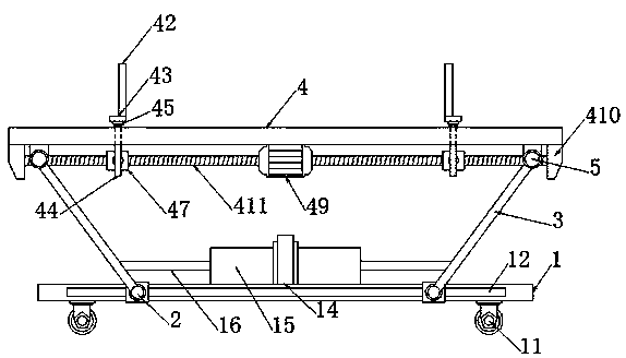
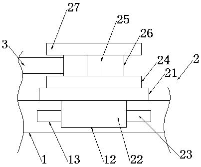
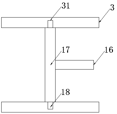
[0023] A quick-assembled smart device mounting frame, comprising a base plate 1, a sliding mechanism 2, a connecting rod 3, a carrier plate 4 and a fixing mechanism 5, two sliding mechanisms 2 are slidably installed on two opposite sides of the base plate 1, four The two sliding mechanisms 2 have the same specifications and are distributed in a rectangular array with each other. A carrier plate 4 is arranged directly above the substrate 1, and fixing mechanisms 5 are fixedly installed at the four corners of the lower end surface of the carrier plate 4. The two fixing mechanisms 5 have the same specification and are distributed in a rectangular array with each other, and the four fixing mechanisms 5 are connected to the four sliding mechanisms 2 through four connecting rods 3 respectively.

[0024] Among them, the four corners of the lower end surface of the substrate 1 are fixedly equipped with universal wheels 11, and the four universal wheels 11 have the same specifications a...


PUM


Abstract

The invention discloses an intelligent equipment mounting rack capable of being quickly assembled. The intelligent equipment mounting rack capable of being quickly assembled comprises a base plate, sliding mechanisms, a connecting rod, a loading plate and fixing mechanisms, wherein two sliding mechanism are glidingly mounted at two opposite side edges of the base plate; the four sliding mechanisms are uniform in size and are mutually distributed in a rectangular array form; the loading plate is arranged right above the base plate; and fixing mechanisms are fixedly mounted at four side corners of the lower end of the loading plate. According to the intelligent equipment mounting rack capable of being quickly assembled, a supporting mechanism is driven by an electric telescoping rod to quickly support by means of linking of a shaft bolt; limiting mechanisms are capable of driving a threaded shaft through a motor, and the threaded shaft is sleeved with a threaded barrel through screw threads, and the limiting mechanism at the upper end is fixedly connected to the threaded sleeve; the threaded barrel cannot rotate through the screw threads and can only move due to the limiting of the corresponding limiting mechanism, and the corresponding limiting mechanism is forced to move together with the threaded barrel; and the limiting mechanisms and the threaded barrel are matched with each other to realize quick limiting.

Description

technical field [0001] The invention belongs to the technical field of intelligent equipment installation, and in particular relates to a rapidly assembled intelligent equipment installation frame. Background technique [0002] In daily use, current smart devices need matching mounting frames to support, limit and fix them. However, the current smart device mounting frames have the problems of low support efficiency and low efficiency of limiting and fixing. For this, it is necessary to design a fast Assembled smart device mount. Contents of the invention [0003] The purpose of the present invention is to provide a quick-assembled smart device mounting frame in order to solve the above problems, which solves the problem of low installation efficiency of the existing smart device mounting frame. [0004] In order to solve the above problems, the present invention provides a technical solution: [0005] A fast-assembling smart device mounting frame, including a base plate...

Claims


Application Information

Patent Timeline
Patent Type & Authority Applications(China)
IPC IPC(8): F16M11/04F16M11/16F16M11/24
CPCF16M11/04F16M11/16F16M11/242
Inventor 杨阳杨琳刘赛男杜耀恒董乐曲世凯徐桢赵宇候永俊邹晖
Owner YANTAI POWER SUPPLY COMPANY OF STATE GRID SHANDONG ELECTRIC POWER
Why Eureka
Try Eureka