Injection molding machine

A technology of injection molding machine and cavity, which is applied in the field of injection molding machines, can solve the problems of poor operability and achieve the effect of improving operability

Active Publication Date: 2019-10-11
SUMITOMO HEAVY IND LTD
7 Cites 1 Cited by

AI-Extracted Technical Summary

Problems solved by technology

However, when using the action button to retract the valve pin until the molding material is cooled and sol...

Method used

[0168] The plasticizing backward judging unit 711 judges whether the plasticizing backward of the injection molding machine 10 is. Here, plastication retreat refers to a situation where the nozzle 320 is separated from the mold device 800 . For example, by detecting a signal indicating that the nozzle 320 is not in contact with the nozzle contact portion 851 , it is determined that the plasticization has retreated. When the nozzle 320 contacts the nozzle contact portion 851 and the gates 825 and 826 are opened, the liquid molding material may leak from the gates 825 and 826 due to residual pressure inside the mold device 800 . Such leakage can be prevented, for example, by judging whether the plasticization has retreated.
[0178] Next, the control device 700 displays an instruction to lower the temperature of the mold device 800 on the display device 760 (step S905). The user looks at the instruction of the display device 760 , turns off the heater 831 , and lowers the temperature of the mold d...

Abstract

The invention relates to an injection molding machine. The present invention addresses the problem of improving the ease of detachment of a cavity plate in a hot runner mold. An injection molding machine according to one embodiment of the present invention is provided with a cavity plate which includes a gate of a cavity space, a runner plate which includes a runner connected to the gate, a valvepin which closes the gate, the runner and the cavity space being cut off from each other or communicating with each other by the valve pin, a drive unit which drives the valve pin, a control unit which controls the drive unit, and an operation unit which performs an operation input for transmitting a command for opening the gate by the control unit, in which the operation unit includes a button, and the control unit continuously transmits a command for opening the gate if the button is pressed.

Technology Topic

Hot runnerMechanical engineering +3

Image

  • Injection molding machine
  • Injection molding machine
  • Injection molding machine

Examples

  • Experimental program(1)

Example Embodiment

[0022] Hereinafter, modes for implementing the present invention will be described with reference to the accompanying drawings. In the drawings, the same or corresponding structures are marked with the same or corresponding symbols to omit description.
[0023] (Injection molding machine)
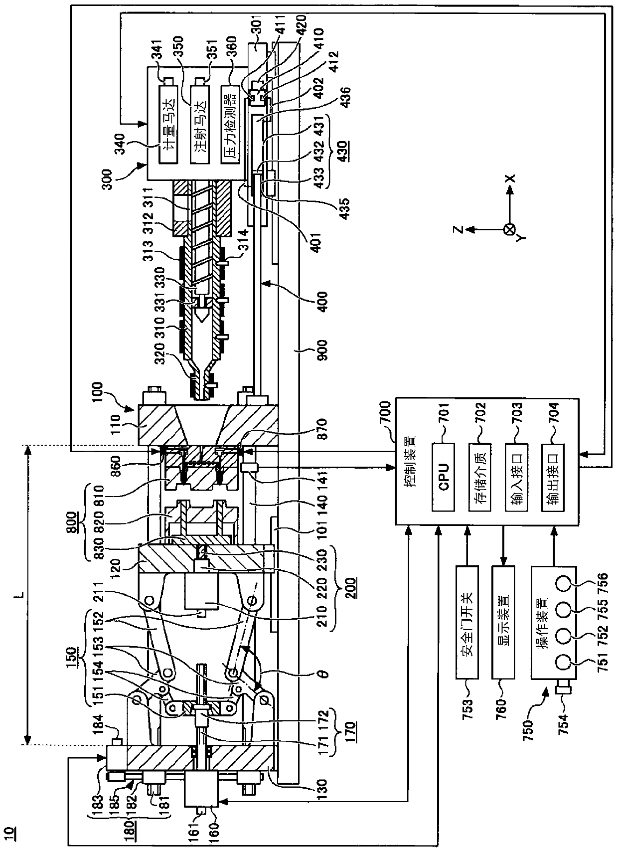
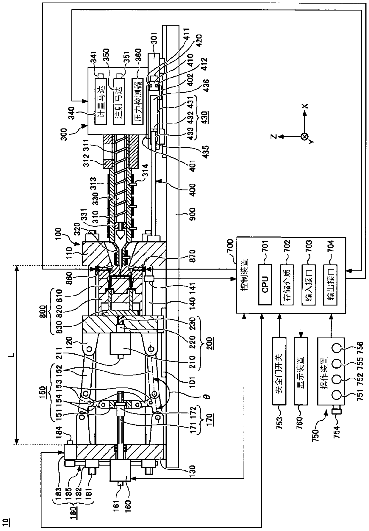
[0024] figure 1 It is a figure which shows the state at the time of completion|finish of mold opening of the injection molding machine of one Embodiment. figure 2 It is a figure which shows the state at the time of mold clamping of the injection molding machine which concerns on one Embodiment. Figure 1 to Figure 2 Among them, the X direction, the Y direction, and the Z direction are mutually perpendicular directions. The X direction and the Y direction indicate the horizontal direction, and the Z direction indicates the vertical direction. When the mold clamping device 100 is a horizontal type, the X direction is the mold opening and closing direction, and the Y direction is the width direction of the injection molding machine 10 . like Figure 1 to Figure 2 As shown, the injection molding machine 10 includes a mold clamping device 100 , an ejector device 200 , an injection device 300 , a moving device 400 , a control device 700 , and a frame 900 . Hereinafter, each constituent element of the injection molding machine 10 will be described.
[0025] (Clamping device)
[0026] In the description of the mold clamping device 100, the moving direction of the movable platen 120 during mold closing ( figure 1 and figure 2 The middle and right direction) is the front, and the moving direction of the movable platen 120 when the mold is opened ( figure 1 and figure 2 Center-left direction) will be described as the rear.
[0027] The mold clamping device 100 performs mold closing, mold clamping, and mold opening of the mold device 800 . The mold clamping device 100 is, for example, a horizontal type, and the mold opening and closing direction is a horizontal direction. The mold clamping device 100 includes a fixed platen 110 , a movable platen 120 , a toggle seat 130 , a connecting rod 140 , a toggle mechanism 150 , a mold clamping motor 160 , a motion conversion mechanism 170 and a mold thickness adjustment mechanism 180 .
[0028] The fixed pressing plate 110 is fixed to the frame 900 . A stationary mold 810 is attached to the surface of the fixed platen 110 facing the movable platen 120 .
[0029] The movable platen 120 is movable relative to the frame 900 in the mold opening and closing direction. Guides 101 for guiding the movable platen 120 are laid on the frame 900 . The movable mold 820 is attached to the surface of the movable platen 120 facing the fixed platen 110 .
[0030] The movable platen 120 is moved forward and backward with respect to the fixed platen 110 to perform mold closing, mold clamping, and mold opening. A mold device 800 is constituted by the fixed mold 810 and the movable mold 820 .
[0031] The toggle seat 130 is connected to the fixed platen 110 with a gap therebetween, and is mounted on the frame 900 movably in the mold opening and closing direction. In addition, the toggle seat 130 can also move freely along the guides laid on the frame 900 . The guide of the toggle seat 130 may be the same as the guide 101 of the movable platen 120 .
[0032] In addition, in this embodiment, the fixed pressure plate 110 is fixed to the frame 900, and the toggle seat 130 is movable relative to the frame 900 in the mold opening and closing direction, but the toggle seat 130 may be fixed to the frame 900, and the fixed pressure plate 110 is relative to the frame. 900 can move freely along the mold opening and closing direction.
[0033] The connecting rod 140 connects the fixed pressure plate 110 and the toggle seat 130 with an interval L between them in the mold opening and closing direction. A plurality of connecting rods 140 (eg, four) may be used. Each connecting rod 140 is parallel to the mold opening and closing direction, and extends according to the mold clamping force. At least one of the connecting rods 140 may be provided with a connecting rod strain detector 141 that detects the strain of the connecting rod 140 . The connecting rod strain detector 141 transmits a signal indicating the detection result thereof to the control device 700 . The detection result of the tie-rod strain detector 141 is used for detection of the clamping force or the like.
[0034] In addition, in the present embodiment, the connecting rod strain detector 141 is used as the mold clamping force detector for detecting the mold clamping force, but the present invention is not limited to this. The clamping force detector is not limited to the strain gauge, but may also be of a piezoelectric type, a capacitive type, a hydraulic type, an electromagnetic type, and the like, and its installation position is also not limited to the connecting rod 140 .
[0035] The toggle mechanism 150 is disposed between the movable platen 120 and the toggle seat 130 , and moves the movable platen 120 relative to the toggle seat 130 in the mold opening and closing direction. The toggle mechanism 150 is composed of a cross head 151, a pair of link groups, and the like. Each link group has a first link 152 and a second link 153 that are flexibly connected by pins or the like. The first link 152 is swingably attached to the movable platen 120 by a pin or the like, and the second link 153 is swingably attached to the toggle seat 130 by a pin or the like. The second link 153 is attached to the crosshead 151 via the third link 154 . When the crosshead 151 is moved forward and backward relative to the toggle seat 130 , the first link 152 and the second link 153 are bent and extended, and the movable platen 120 is moved forward and backward relative to the toggle seat 130 .
[0036] In addition, the structure of the toggle mechanism 150 is not limited to figure 1 and figure 2 shown structure. E.g figure 1 and figure 2 Although the number of nodes of each link group is 5, it may be 4, and one end of the third link 154 may be a node where the first link 152 and the second link 153 are coupled.
[0037] The mold clamping motor 160 is attached to the toggle seat 130 to operate the toggle mechanism 150 . The mold clamping motor 160 moves the crosshead 151 forward and backward relative to the toggle seat 130 , thereby bending and extending the first link 152 and the second link 153 , and moving the movable platen 120 forward and backward relative to the toggle seat 130 . The mold clamping motor 160 is directly connected to the motion conversion mechanism 170, but may be connected to the motion conversion mechanism 170 via a belt, a pulley, or the like.
[0038] The motion converting mechanism 170 converts the rotational motion of the mold clamping motor 160 into the linear motion of the crosshead 151 . The motion converting mechanism 170 includes a threaded shaft 171 and a nut 172 screwed to the threaded shaft 171 . Balls or rollers may be interposed between the threaded shaft 171 and the nut 172 .
[0039] The mold clamping device 100 performs a mold closing process, a mold clamping process, a mold opening process, and the like under the control of the control device 700 .
[0040] In the mold closing process, the mold clamping motor 160 is driven to advance the crosshead 151 to the mold closing end position at a set speed, thereby advancing the movable platen 120 to bring the movable mold 820 into contact with the stationary mold 810 . The position and speed of the crosshead 151 are detected using, for example, the mold clamping motor encoder 161 or the like. The mold clamping motor encoder 161 detects the rotation of the mold clamping motor 160 and transmits a signal indicating the detection result to the control device 700 . In addition, the crosshead position detector for detecting the position of the crosshead 151 and the crosshead speed detector for detecting the speed of the crosshead 151 are not limited to the mold clamping motor encoder 161, and general detectors can be used. In addition, the movable platen position detector for detecting the position of the movable platen 120 and the movable platen speed detector for detecting the speed of the movable platen 120 are not limited to the mold clamping motor encoder 161, and general detectors can be used.
[0041] In the mold clamping step, the mold clamping motor 160 is further driven to further advance the crosshead 151 from the mold closing end position to the mold closing position, thereby generating a mold clamping force. When the mold is closed, a cavity space 801 is formed between the movable mold 820 and the fixed mold 810 (refer to figure 2 ), the injection device 300 fills the cavity space 801 with liquid molding material. A molded product is obtained by curing the filled molding material. The number of cavity spaces 801 may be plural, and in this case, plural molded products can be obtained at the same time.
[0042] In the mold opening process, the mold clamping motor 160 is driven to retract the crosshead 151 at a set speed to the mold opening end position, thereby retracting the movable platen 120 to separate the movable mold 820 from the fixed mold 810 . After that, the ejector 200 ejects the molded product from the movable mold 820 .
[0043] The setting conditions in the mold closing process and the mold clamping process are collectively set as a series of setting conditions. For example, the speed and position of the crosshead 151 in the mold closing process and the mold clamping process (including the mold closing start position, the speed switching position, the mold closing end position, and the mold closing position), and the mold clamping force are determined as a series of set conditions. and set. The mold closing start position, the speed switching position, the mold closing end position, and the mold closing position are arranged in order from the rear side toward the front, and indicate the start point and the end point of the section where the speed is set. Set the speed for each section. The speed switching position may be one or multiple. It is also possible not to set the speed switching position. Only one of the mold clamping position and the mold clamping force may be set.
[0044] The setting conditions in the mold opening process are also set in the same manner. For example, the speed and position of the crosshead 151 in the mold opening process (including the mold opening start position, the speed switching position, and the mold opening end position) are collectively set as a series of setting conditions. The mold-opening start position, the speed switching position, and the mold-opening end position are arranged in order from the front side toward the rear, and indicate the start point and the end point of the section where the speed is set. Set the speed for each section. The speed switching position may be one or multiple. It is also possible not to set the speed switching position. The mold opening start position and the mold closing position may be the same position. In addition, the mold opening end position and the mold closing start position may be the same position.
[0045] In addition, the speed, position, etc. of the movable platen 120 may be set instead of the speed, position, etc. of the crosshead 151 . In addition, the mold clamping force may be set instead of the position of the crosshead (for example, the mold clamping position) and the position of the movable platen.
[0046] The toggle mechanism 150 amplifies the driving force of the mold clamping motor 160 and transmits it to the movable platen 120 . Its magnification is also called toggle magnification. The toggle magnification changes according to the angle θ formed by the first link 152 and the second link 153 (hereinafter, also referred to as "link angle θ"). The link angle θ is obtained from the position of the crosshead 151 . When the connecting rod angle θ is 180°, the toggle override is the largest.
[0047] When the thickness of the mold device 800 changes due to replacement of the mold device 800, temperature change of the mold device 800, or the like, the mold thickness is adjusted so that a predetermined mold clamping force is obtained at the time of mold clamping. In the die thickness adjustment, for example, the distance L between the fixed platen 110 and the toggle seat 130 is adjusted so that the link angle θ of the toggle mechanism 150 becomes a predetermined angle when the movable die 820 and the die in contact with the fixed die 810 come into contact with each other. .
[0048] The mold clamping device 100 includes a mold thickness adjustment mechanism 180 that adjusts the mold thickness by adjusting the interval L between the fixed platen 110 and the toggle seat 130 . The die thickness adjusting mechanism 180 includes: a threaded shaft 181 formed at the rear end of the connecting rod 140; a nut 182 rotatably held on the toggle seat 130; Nut 182 rotates.
[0049] A threaded shaft 181 and a nut 182 are provided on each connecting rod 140 . The rotation of the die thickness adjustment motor 183 can be transmitted to the plurality of nuts 182 via the rotation transmission portion 185 . The plurality of nuts 182 can be rotated synchronously. In addition, each of the plurality of nuts 182 can be rotated by changing the transmission path of the rotation transmission portion 185 .
[0050] The rotation transmission portion 185 is constituted by, for example, a gear or the like. In this case, a driven gear is formed on the outer circumference of each nut 182, a drive gear is attached to the output shaft of the die thickness adjustment motor 183, and an intermediate gear meshed with the plurality of driven gears and the drive gear is rotatably held by the toggle. at the center of the joint seat 130 . In addition, the rotation transmission part 185 may be comprised with a belt, a pulley, etc. instead of a gear.
[0051] The operation of the die thickness adjustment mechanism 180 is controlled by the control device 700 . The control device 700 drives the die thickness adjusting motor 183 to rotate the nut 182 , thereby adjusting the position of the toggle seat 130 that keeps the nut 182 rotatably relative to the fixed pressure plate 110 , thereby adjusting the distance between the fixed pressure plate 110 and the toggle seat 130 interval L.
[0052] In addition, the nut 182 may be fixed to the toggle seat 130 , and the connecting rod 140 may be rotatably held with respect to the fixed pressure plate 110 . In this case, the interval L can be adjusted by rotating the connecting rod 140 .
[0053] In addition, the nut 182 may be fixed to the fixed pressure plate 110 , and the connecting rod 140 may be rotatably held with respect to the toggle seat 130 . In this case, the interval L can be adjusted by rotating the connecting rod 140 .
[0054] The interval L is detected using the die thickness adjustment motor encoder 184 . The mold thickness adjustment motor encoder 184 detects the rotation amount and the rotation direction of the mold thickness adjustment motor 183 , and transmits a signal indicating the detection result to the control device 700 . The detection result of the die thickness adjustment motor encoder 184 is used in monitoring and controlling the position and interval L of the toggle seat 130 . In addition, the toggle seat position detector for detecting the position of the toggle seat 130 and the interval detector for detecting the interval L are not limited to the mold thickness adjustment motor encoder 184, and general detectors can be used.
[0055] The die thickness adjustment mechanism 180 adjusts the interval L by rotating one of the screw shaft 181 and the nut 182 that are screwed to each other. A plurality of mold thickness adjustment mechanisms 180 may be used, or a plurality of mold thickness adjustment motors 183 may be used.
[0056] In addition, although the mold clamping apparatus 100 of this embodiment is a horizontal type in which the mold opening and closing direction is a horizontal direction, it may be a vertical type in which the mold opening and closing direction is an up-down direction.
[0057] In addition, although the mold clamping apparatus 100 of this embodiment has the mold clamping motor 160 as a drive source, a hydraulic cylinder may be provided instead of the mold clamping motor 160 . In addition, the mold clamping device 100 may have a linear motor for mold opening and closing and an electromagnet for mold clamping.
[0058] (ejector device)
[0059] In the description of the ejector device 200, as in the description of the mold clamping device 100, the moving direction of the movable platen 120 ( figure 1 and figure 2 The middle and right direction) is the front, and the moving direction of the movable platen 120 when the mold is opened ( figure 1 and figure 2 Center-left direction) will be described as the rear.
[0060] The ejector 200 ejects the molded product from the mold device 800 . The ejecting device 200 has an ejecting motor 210 , a motion converting mechanism 220 , an ejecting rod 230 and the like.
[0061] The ejection motor 210 is mounted on the movable platen 120 . The ejector motor 210 is directly connected to the motion conversion mechanism 220, but may be connected to the motion conversion mechanism 220 via a belt, a pulley, or the like.
[0062] The motion converting mechanism 220 converts the rotational motion of the ejector motor 210 into the linear motion of the ejector rod 230 . The motion conversion mechanism 220 includes a threaded shaft and a nut screwed to the threaded shaft. Balls or rollers can be sandwiched between the threaded shaft and the nut.
[0063] The ejector rod 230 can move forward and backward freely in the through hole of the movable platen 120 . The front end portion of the ejector rod 230 is in contact with the movable member 830 which is provided in the movable mold 820 so as to be able to move forward and backward. The front end portion of the ejector rod 230 may or may not be connected to the movable member 830 .
[0064] The ejector 200 performs the ejection process under the control of the control device 700 .
[0065] In the ejection step, the ejector motor 210 is driven to advance the ejector rod 230 from the standby position to the ejection position at a set speed, thereby advancing the movable member 830 to eject the molded product. After that, the ejector motor 210 is driven to retract the ejector rod 230 at the set speed, and the movable member 830 is retracted to the original standby position. The position and speed of the ejector rod 230 are detected, for example, using the ejector motor encoder 211 . The ejector motor encoder 211 detects the rotation of the ejector motor 210 and transmits a signal indicating the detection result to the control device 700 . In addition, the ejector lever position detector for detecting the position of the ejector lever 230 and the ejector lever speed detector for detecting the speed of the ejector lever 230 are not limited to the ejector motor encoder 211, and general detectors can be used.
[0066] (injection device)
[0067] In the description of the injection device 300, different from the description of the mold clamping device 100 and the description of the ejector device 200, the movement direction of the screw 330 during filling ( figure 1 and figure 2 The center left direction) is the front, and the moving direction of the screw 330 during measurement ( figure 1 and figure 2 Center-right direction) will be described as the rear.
[0068] The injection device 300 is provided on a sliding base 301 that can move forward and backward relative to the frame 900 , and can move forward and backward relative to the mold device 800 . The injection device 300 is in contact with the mold device 800 and fills the cavity space 801 in the mold device 800 with a molding material. The injection device 300 includes, for example, a cylinder 310 , a nozzle 320 , a screw 330 , a metering motor 340 , an injection motor 350 , a pressure detector 360 , and the like.
[0069] The cylinder 310 heats the molding material supplied to the inside from the supply port 311 . The molding material includes, for example, resin and the like. The molding material is formed in a granular form, for example, and is supplied to the supply port 311 in a solid state. The supply port 311 is formed at the rear of the cylinder block 310 . A cooler 312 such as a water-cooled cylinder is provided on the outer periphery of the rear portion of the cylinder block 310 . A heater 313 such as a belt heater and a temperature detector 314 are provided on the outer periphery of the cylinder block 310 ahead of the cooler 312 .
[0070] The cylinder block 310 is along the axial direction of the cylinder block 310 ( figure 1 and figure 2 in the left and right directions) is divided into multiple areas. A heater 313 and a temperature detector 314 are provided in each area. The control device 700 controls the heater 313 so that the temperature detected by the temperature detector 314 for each area becomes the set temperature.
[0071] The nozzle 320 is provided at the front end portion of the cylinder block 310 and is pressed against the mold device 800 . A heater 313 and a temperature detector 314 are provided on the outer periphery of the nozzle 320 . The control device 700 controls the heater 313 so that the detected temperature of the nozzle 320 becomes the set temperature.
[0072] The screw 330 is arranged in the cylinder 310 so as to be rotatable and advance and retreat freely. When the screw 330 is rotated, the molding material is sent forward along the spiral groove of the screw 330 . The molding material is gradually melted by the heat from the cylinder 310 while being sent forward. As the liquid molding material is sent to the front of the screw 330 and accumulated in the front part of the cylinder 310 , the screw 330 retreats. After that, when the screw 330 is advanced, the liquid molding material accumulated in the front of the screw 330 is injected from the nozzle 320 and filled in the mold device 800 .
[0073] The check ring 331 is attached to the front of the screw 330 so as to be able to move forward and backward as a check valve that prevents the molding material from flowing backward from the front to the rear of the screw 330 when the screw 330 is pushed forward.
[0074] When the screw 330 is advanced, the check ring 331 is pushed backward by the pressure of the molding material in front of the screw 330, and retreats with respect to the screw 330 to a closed position that blocks the flow path of the molding material (refer to figure 2 )until. Thereby, the backflow of the molding material accumulated in the front of the screw 330 is prevented.
[0075] On the other hand, when the screw 330 is rotated, the non-return ring 331 is pushed forward by the pressure of the molding material sent forward along the helical groove of the screw 330, and moves forward with respect to the screw 330 to open the flow path of the molding material open location (reference figure 1 )until. Thereby, the molding material is sent to the front of the screw 330 .
[0076] The check ring 331 may be any of a co-rotation type that rotates with the screw 330 and a non-co-rotation type that does not rotate with the screw 330 .
[0077] In addition, the injection device 300 may have a drive source for advancing and retreating the check ring 331 with respect to the screw 330 between the open position and the closed position.
[0078] The metering motor 340 rotates the screw 330 . The drive source for rotating the screw 330 is not limited to the metering motor 340, and may be, for example, a hydraulic pump or the like.
[0079] The injection motor 350 advances and retracts the screw 330 . Between the injection motor 350 and the screw 330 , a motion conversion mechanism or the like that converts the rotational motion of the injection motor 350 into the linear motion of the screw 330 is provided. The motion conversion mechanism has, for example, a threaded shaft and a nut screwed to the threaded shaft. Balls or rollers, etc. can be provided between the threaded shaft and the nut. The drive source for advancing and retracting the screw 330 is not limited to the injection motor 350, and may be, for example, a hydraulic cylinder or the like.
[0080] The pressure detector 360 detects the force transmitted between the injection motor 350 and the screw 330 . The detected force is converted into pressure by the control device 700 . The pressure detector 360 is provided in the force transmission path between the injection motor 350 and the screw 330 , and detects the force acting on the pressure detector 360 .
[0081] The pressure detector 360 transmits a signal indicating the detection result thereof to the control device 700 . The detection result of the pressure detector 360 is used to control and monitor the pressure received by the screw 330 from the molding material, the back pressure on the screw 330, the pressure with which the screw 330 acts on the molding material, and the like.
[0082] The injection device 300 performs a measuring process, a filling process, a pressure maintaining process, and the like under the control of the control device 700 .
[0083] In the weighing step, the weighing motor 340 is driven to rotate the screw 330 at a set rotational speed, so that the molding material is sent forward along the spiral groove of the screw 330 . Following this, the molding material is gradually melted. As the liquid molding material is sent to the front of the screw 330 and accumulated in the front part of the cylinder 310 , the screw 330 retreats. The rotational speed of the screw 330 is detected using, for example, the metering motor encoder 341 . The weighing motor encoder 341 detects the rotation of the weighing motor 340 and transmits a signal indicating the detection result to the control device 700 . In addition, the screw rotation speed detector for detecting the rotation speed of the screw 330 is not limited to the metering motor encoder 341, and a general detector can be used.
[0084] In the measuring process, in order to restrict the rapid retraction of the screw 330 , the injection motor 350 may be driven to apply a set back pressure to the screw 330 . The back pressure with respect to the screw 330 is detected using, for example, the pressure detector 360 . The pressure detector 360 transmits a signal indicating the detection result thereof to the control device 700 . When the screw 330 is retracted to the measurement end position and a predetermined amount of molding material is accumulated in front of the screw 330, the weighing process ends.
[0085] In the filling step, the injection motor 350 is driven to advance the screw 330 at a predetermined speed, and the liquid molding material accumulated in the front of the screw 330 is filled into the cavity space 801 in the mold device 800 . The position and speed of the screw 330 are detected, for example, using the injection motor encoder 351 . The injection motor encoder 351 detects the rotation of the injection motor 350 and transmits a signal indicating the detection result to the control device 700 . When the position of the screw 330 reaches the set position, switching from the filling process to the pressure holding process (so-called, V/P switching) is performed. The position where the V/P switching is performed is also referred to as the V/P switching position. The setting speed of the screw 330 can be changed according to the position and time of the screw 330, and the like.
[0086] In addition, in the filling process, after the position of the screw 330 reaches the set position, the screw 330 may be temporarily stopped at the set position, and then the V/P switching may be performed. Immediately before the V/P switching, instead of stopping the screw 330, the screw 330 may be moved forward or backward at a slight speed. In addition, the screw position detector for detecting the position of the screw 330 and the screw speed detector for detecting the speed of the screw 330 are not limited to the injection motor encoder 351, and general detectors can be used.
[0087] In the holding pressure step, the injection motor 350 is driven to push the screw 330 forward, and the pressure of the molding material (hereinafter, also referred to as "holding pressure") at the tip of the screw 330 is maintained at the set pressure and remains in the cylinder The molding material within the body 310 is pushed toward the mold arrangement 800 . The insufficient amount of molding material due to cooling shrinkage in the mold device 800 can be supplemented. The holding pressure is detected, for example, using pressure detector 360 . The pressure detector 360 transmits a signal indicating the detection result thereof to the control device 700 . The set value of the holding pressure can be changed according to the elapsed time or the like since the start of the pressure holding process.
[0088] During the pressure maintaining process, the molding material in the cavity space 801 in the mold device 800 is gradually cooled, and when the pressure maintaining process ends, the entrance of the cavity space 801 is closed by the solidified molding material. This state is called gate sealing and prevents the backflow of the molding material from the cavity space 801 . After the pressure-holding step, the cooling step is started. In the cooling step, solidification of the molding material in the cavity space 801 is performed. In order to shorten the molding cycle time, the metering process can be performed during the cooling process.
[0089] In addition, although the injection apparatus 300 of this embodiment is a coaxial reciprocating screw type, it may be a pre-plasticizing type or the like. The injection device of the pre-plasticization system supplies the molding material melted in the plasticizing cylinder to the injection cylinder, and injects the molding material from the injection cylinder into the mold device. The screw is freely rotatable or freely rotatable and can advance and retreat freely in the plasticizing cylinder, and the plunger is freely arranged in the injection cylinder.
[0090] In addition, although the injection device 300 of the present embodiment is a horizontal type in which the axial direction of the cylinder 310 is in the horizontal direction, it may be a vertical type in which the axial direction of the cylinder 310 is in the vertical direction. The mold clamping device combined with the vertical injection device 300 may be a vertical type or a horizontal type. Likewise, the mold clamping device combined with the horizontal injection device 300 may be a horizontal type or a vertical type.
[0091] (mobile device)
[0092] In the description of the moving device 400, as in the description of the injection device 300, the moving direction of the screw 330 at the time of filling ( figure 1 and figure 2 The center left direction) is the front, and the moving direction of the screw 330 during measurement ( figure 1 and figure 2 Center-right direction) will be described as the rear.
[0093] The moving device 400 advances and retreats the injection device 300 with respect to the mold device 800 . Then, the moving device 400 presses the nozzle 320 against the mold device 800 to generate a nozzle contact pressure. The moving device 400 includes a hydraulic pump 410, a motor 420 as a driving source, a hydraulic cylinder 430 as a hydraulic actuator, and the like.
[0094] The hydraulic pump 410 has a first port 411 and a second port 412 . The hydraulic pump 410 is a bidirectionally rotatable pump, and by switching the rotation direction of the motor 420, a hydraulic fluid (eg oil) is sucked from one of the first port 411 and the second port 412 and discharged from the other port to generate hydraulic pressure. In addition, the hydraulic pump 410 can also suck the working fluid from the tank and discharge the working fluid from any one of the first port 411 and the second port 412 .
[0095] The motor 420 operates the hydraulic pump 410 . The motor 420 drives the hydraulic pump 410 with a rotational direction and torque in response to a signal from the control device 700 . The motor 420 may be an electric motor or an electric servo motor.
[0096] The hydraulic cylinder 430 has a cylinder body 431 , a piston 432 and a piston rod 433 . The cylinder body 431 is fixed to the injection device 300 . The piston 432 divides the inside of the cylinder body 431 into a front chamber 435 serving as a first chamber and a rear chamber 436 serving as a second chamber. The piston rod 433 is fixed to the fixed pressing plate 110 .
[0097] The front chamber 435 of the hydraulic cylinder 430 is connected to the first port 411 of the hydraulic pump 410 via the first flow path 401 . The working fluid discharged from the first port 411 is supplied to the front chamber 435 via the first flow path 401, whereby the injection device 300 is pushed forward. The injection device 300 moves forward, and the nozzle 320 is pressed against the stationary mold 810 . The front chamber 435 functions as a pressure chamber that generates the nozzle contact pressure of the nozzle 320 by the pressure of the hydraulic fluid supplied from the hydraulic pump 410 .
[0098] On the other hand, the rear chamber 436 of the hydraulic cylinder 430 is connected to the second port 412 of the hydraulic pump 410 via the second flow path 402 . The hydraulic fluid discharged from the second port 412 is supplied to the rear chamber 436 of the hydraulic cylinder 430 via the second flow path 402, whereby the injection device 300 is pushed rearward. The injection device 300 is retracted, and the nozzle 320 is separated from the stationary mold 810 .
[0099] In addition, in this embodiment, although the movement apparatus 400 contains the hydraulic cylinder 430, this invention is not limited to this. For example, instead of the hydraulic cylinder 430 , an electric motor and a motion conversion mechanism for converting the rotational motion of the electric motor into the linear motion of the injection device 300 may be used.
[0100] (control device)
[0101] The control device 700 is constituted by, for example, a computer such as Figure 1 to Figure 2 As shown, it includes a CPU (Central Processing Unit: Central Processing Unit) 701 , a storage medium 702 such as a memory, an input interface 703 and an output interface 704 . The control device 700 performs various controls by causing the CPU 701 to execute a program stored in the storage medium 702 . In addition, the control device 700 receives signals from the outside through the input interface 703 , and transmits signals to the outside through the output interface 704 .
[0102]The control device 700 repeats the mold closing process, the mold clamping process, the mold opening process, and the like, thereby repeatedly producing a molded product. In addition, the control device 700 performs a measuring process, a filling process, a pressure holding process, and the like during the mold clamping process. A series of actions for obtaining a molded product, for example, an action from the start of the weighing process to the start of the next weighing process is also referred to as "shot" or "molding cycle". In addition, the time required for one shot is also referred to as "molding cycle time".
[0103] One molding cycle includes, for example, a metering process, a mold closing process, a mold clamping process, a filling process, a pressure holding process, a cooling process, a mold opening process, and an ejection process in this order. The order here is the order in which each process starts. The filling process, the pressure holding process, and the cooling process are performed during the period from the start of the mold clamping process to the end of the mold clamping process. The end of the mold clamping process coincides with the start of the mold opening process. In addition, in order to shorten the molding cycle time, a plurality of steps may be performed simultaneously. For example, the weighing process may be performed in the cooling process of the previous molding cycle, and in this case, the mold closing process may be performed at the beginning of the molding cycle. Also, the filling process may be started during the mold closing process. Also, the ejection process may be started during the mold opening process.
[0104] The control device 700 is connected to the operation device 750 and the display device 760 .
[0105] The operation device 750 accepts the user's input operation, and outputs a signal corresponding to the input operation to the control device 700 . Further, the operation device 750 includes a first button 751 , a second button 752 , a safety door switch 753 , an emergency stop switch 754 , a mold closing operation button 755 , and an injection operation button 756 .
[0106] When the first button 751 is pressed, the first button 751 transmits a signal instructing to open the gate to the control device 700 . The control device 700 opens a gate for supplying a liquid molding material to the cavity space 801 . The first button 751 transmits such a signal only while the first button 751 is being held down.
[0107] On the other hand, when the second button 752 is pressed, the second button 752 transmits to the control device 700 a signal instructing to open the gate. The control device 700 opens a gate for supplying a liquid molding material to the cavity space 801 . In the case of the second button 752, once the button is pressed, the second button 752 continues to transmit such a signal. That is, even if the second button 752 is not held down, the second button 752 continues to transmit a signal, for example, until the second button 752 is pressed again, and this state is maintained.
[0108] The safety door switch 753 is a switch that is turned on when the safety door included in the injection molding machine 10 is opened. If the safety door switch 753 is turned on, the injection molding machine 10 stops all operations, and the functions of the injection molding machine 10 are disabled.
[0109] As will be described later, while the second button 752 is pressed and the second button 752 continues to transmit a signal instructing to open the gate, the user approaches the injection molding machine 10 to remove or attach the cavity plate. In order to approach the injection molding machine 10, the safety door is opened, and the safety door switch 753 is turned on. Actually, all the functions of the injection molding machine 10 will be disabled. However, while the second button 752 is pressed and the second button 752 continues to transmit a signal instructing to open the gate, even when the safety door switch 753 is turned on, the gate opening does not fail and the gate remains open.
[0110] When the emergency stop switch 754 is pressed, the injection molding machine 10 stops all operations similarly to the case where the safety door switch 753 is turned on, and the functions of the injection molding machine 10 are disabled. Also in this case, similarly to the case where the safety door switch 753 is turned on, while the second button 752 is pressed and the second button 752 continues to transmit a signal instructing to open the gate, the gate opening does not fail and remains open. state.
[0111] In addition, when another operation is performed by the operation device 750, the gate opening does not fail and the gate remains open while the second button 752 is pressed and the second button 752 continues to transmit a signal instructing to open the gate. . Such other operations include, for example, the mold closing operation button 755 and the injection operation button 756 .
[0112] When the mold closing operation button 755 is pressed, the movable platen 120 moves forward relative to the fixed platen 110 to perform mold closing. When the injection operation button 756 is pressed, the injection device 300 performs the filling process, the pressure maintaining process, and the like under the control of the control device 700 .
[0113] However, when the mold closing operation button 755 or the injection operation button 756 is pressed, the gate opening does not fail while the second button 752 is pressed and the second button 752 continues to transmit a signal instructing to open the gate. Keep it open.
[0114] The display device 760 displays an operation screen corresponding to the input operation in the operation device 750 under the control of the control device 700 .
[0115] The operation screen is used for setting and the like of the injection molding machine 10 . Several operation screens are prepared, which can be displayed in switching or overlapping. The user operates the operation device 750 while viewing the operation screen displayed on the display device 760 , thereby setting the injection molding machine 10 (including input of setting values) and the like.
[0116] The operation device 750 and the display device 760 are constituted by, for example, a touch panel, and may be integrated. Buttons such as the first button 751 and the second button 752 may be constituted by a touch panel, or may be constituted by physical push buttons. In addition, although the operation device 750 and the display device 760 in this embodiment are integrated, they may be provided independently. In addition, a plurality of operation devices 750 may be provided.
[0117] (Mold Device)
[0118] Next, refer to Figures 3 to 5 A mold apparatus 800 according to an embodiment will be described. image 3 It is a cross-sectional view showing the mold device 800 at the time of mold opening.
[0119] The mold apparatus 800 of one embodiment is a mold apparatus that can be used to mold components made of plastic.
[0120] The mold apparatus 800 is a so-called hot runner type mold apparatus, and the sprue 852 and the runner 853 are always heated. Therefore, when the liquid molding material filled in the cavity space 801 of the mold is cooled and solidified, a mechanism is provided to cut off the runner 853 from the solidified molded product portion (in the cavity space). The cut-off mechanism is equivalent to Figures 3 to 4 Gate valve mechanisms 860 and 870 in the . but, Figures 3 to 4 , in order to prevent the diagram from becoming complicated, in Figure 5 The gate valve mechanism is shown in detail.
[0121] The mold device 800 includes a fixed mold 810 and a movable mold 820 . The fixed mold 810 is mounted on the fixed platen 110, and the movable mold 820 is mounted on the movable platen 120 (refer to figure 1 and figure 2 ).
[0122] The stationary mold 810 has a cavity plate 811 and a flow channel plate 812 . image 3 In the figure, the cavity plate 811 is indicated by hatching with a wide interval, and the flow channel plate 812 is indicated by hatching with a narrow interval. The cavity plate 811 and the flow channel plate 812 are configured to be separable. Specifically in Figure 7 stated otherwise.
[0123] Inside the runner plate 812, a sprue 852, which becomes a channel of a molten liquid molding material, is formed, and a runner 853 is formed in connection with the sprue 852. One end of the sprue 852 is connected to the nozzle contact portion 851 formed on the side surface of the stationary mold 810 . The nozzle 320 of the injection device 300 is connected to the nozzle contact portion 851 (refer to figure 1 and figure 2 ).
[0124] The runner 853 is formed so that the runner 852 is connected to the connecting portion toward the runner 852 . image 3 In the vertical direction of the branch, it is connected to the gate 825 at the upper part and connected to the gate 826 at the lower part. A plurality of heaters 831 for heating the sprue 852 and the runner 853 are arranged around the sprue 852 and the runner 853 . In order to keep the molding material in the sprue 852 and the runner 853 in a molten state, the temperature of the heater 831 is controlled based on the detection value of a temperature sensor (not shown) embedded in the stationary mold 810 .
[0125] image 3 The state shown is a state in which the mold device 800 is opened, and when the mold is closed, the movable mold 820 moves in the direction indicated by the hollow arrow.
[0126] Figure 4 The mold device 800 in the mold-closed state is shown. Figure 4 Among them, the so-called parting line is represented by the line PL at the junction of the fixed mold 810 and the movable mold 820 .
[0127] In addition, at the boundary between the stationary mold 810 and the movable mold 820, a cavity space 801a is formed in the space connecting the gate 825. In addition, a cavity space 801b is formed in the space connecting the gate 826 .
[0128] The liquid molding material flows in the runner 853 , fills the cavity space 801 a via the gate 825 , and fills the cavity space 801 b via the gate 826 . A molded product is formed by cooling and solidifying the filled liquid molding material. The mold apparatus 800 is a so-called double-cavity mold apparatus for forming molded products in the cavity spaces 801a and 801b, respectively.
[0129] After the liquid molding material is solidified in the mold device 800 and a molded product is formed, the movable mold 820 is moved (mold opening). After that, the movable member 830 is advanced by the ejector rod 230 to eject the molded product, whereby the molded product solidified in the cavity spaces 801a and 801b is separated from the movable mold 820 and taken out.
[0130] Gate valve mechanisms 860 and 870 are provided in the runner 853 . The gate valve mechanism 860 opens or closes the gate 825 , and the gate valve mechanism 870 opens or closes the gate 826 .
[0131] The gate valve mechanism 860 includes a valve pin 861 , an air cylinder 862 , and a solenoid valve 866 . The valve pin 861 is provided so as to be able to move in the flow passage 853 and to advance and retreat in the axial direction, thereby closing or opening the gate 825 . Air cylinder 862 drives valve pin 861 . Solenoid valve 866 controls actuation based on cylinder 862 .
[0132] Similarly, the gate valve mechanism 870 includes a valve pin 871 , an air cylinder 872 , and a solenoid valve 876 . The valve pin 871 is provided so as to be able to move in the flow passage 853 and to advance and retreat in the axial direction, thereby closing or opening the gate 826 . Air cylinder 872 drives valve pin 871 . The solenoid valve 876 is controlled based on the actuation of the air cylinder 872 .
[0133] Figure 5 It is a figure which shows the front-end|tip part of the valve pin 861, its vicinity, and the gate valve mechanism 860. Figure 5 (a) shows the state in which the gate 825 is closed, Figure 5 (b) shows a state in which the gate 825 is opened. In addition, the following "the direction in which the valve pin 861 advances" means Figure 5 The direction of the hollow arrow shown in (a), "the direction in which the valve pin 861 is retracted" represents Figure 5 The directions of the hollow arrows shown in (b). and, sometimes Figure 5 (a), Figure 5 The arrow direction shown in (b) is referred to as the axial direction of the valve pin 861 .
[0134] The distal end portion of the valve pin 861 is formed to have an outer diameter d that fits into the inner diameter of the gate 825 . like Figure 5 As shown in (a), when the valve pin 861 advances in the direction of the hollow arrow in the figure and the valve pin 861 is inserted into the gate 825, the gate 825 is closed and the space between the runner 853 and the cavity space 801a is cut off. As a result, the liquid molding material cannot flow into the cavity space 801a from the runner 853 .
[0135] On the other hand, if Figure 5 As shown in (b), when the valve pin 861 retreats in the direction of the hollow arrow in the figure and the valve pin 861 is pulled out from the gate 825, the gate 825 is opened and the runner 853 and the cavity space 801a are communicated. Thereby, the liquid molding material can flow into the cavity space 801 a from the runner 853 via the gate 825 .
[0136] The drive mechanism of the gate valve mechanism 860 is constituted by an air cylinder 862 . Inside the cylinder 862, a piston 863 and a valve pin 861 are arranged. The valve pin 861 is fixed to the piston 863 or formed integrally with the piston 863 . When the cylinder 862 is driven by supplying compressed air, the piston 863 moves, and the valve pin 861 advances or retreats.
[0137] Specifically, as Figure 5 As shown in (a), when compressed air is supplied from the air supply/discharge port 865 through the solenoid valve 866, the piston 863 advances together with the valve pin 861 in the direction of the hollow arrow in the figure inside the cylinder 862. Thereby, the valve pin 861 is inserted into the gate 825, and the gate 825 is closed.
[0138] and, as Figure 5 As shown in (b), when compressed air is supplied from the air supply/discharge port 864 through the solenoid valve 866, the piston 863 and the valve pin 861 are retracted in the direction of the hollow arrow in the figure inside the cylinder 862. Thereby, the valve pin 861 is pulled out from the gate 825, and the gate 825 is opened.
[0139] The solenoid valve 866 is, for example, a three-port solenoid valve, and has one intake port and two exhaust ports, and the intake port is connected to the compressor. By electrically switching the position of the solenoid valve, the supply of compressed air to the air supply and discharge port 864 and the air supply and discharge port 865 can be switched. For example, when the solenoid valve is set to one side, compressed air is supplied from the intake port to the air supply and discharge port 864, and the air inside the cylinder 862 is exhausted from one of the exhaust ports. When the solenoid valve is positioned on the other side, compressed air is supplied from the intake port to the air supply and discharge port 865, and the air inside the cylinder 862 is exhausted from the other exhaust port.
[0140] Control by the solenoid valve 866 is performed by the control device 700 . The control device 700 controls the solenoid valve 866 according to the schedule at the time of injection molding. Alternatively, the solenoid valve 866 is controlled by signals from the first button 751 and the second button 752 of the operation device 750 .
[0141] In addition, the driving of the gate valve mechanism 860 is not limited to an air cylinder, and may be a hydraulic cylinder, a servo motor, or a combination of these.
[0142] and, Figure 5 The tip portion of the valve pin 861 and its vicinity, and the gate valve mechanism 860 have been described above, but the same applies to the tip portion of the valve pin 871 and its vicinity, and the gate valve mechanism 870 .
[0143] (Operation of gate during injection molding)
[0144] Here, reference is made to a flowchart ( Image 6 ) to explain the operation of the gate during injection molding.
[0145] First, in the mold closing process, the mold clamping device 100 drives the mold clamping motor 160 to advance the crosshead 151 to the mold closing end position, thereby advancing the movable platen 120 to bring the movable mold 820 into contact with the stationary mold 810 .
[0146] The mold clamping device 100 further drives the mold clamping motor 160 to further advance the crosshead 151 from the mold closing end position to the mold closing position, thereby generating a mold clamping force. When the mold is closed, a cavity space 801 is formed between the movable mold 820 and the fixed mold 810 (refer to figure 2 ) (step S601).
[0147] Next, the control device 700 controls the gate valve mechanisms 860 and 870 to supply compressed air to the air supply and discharge ports 864 and 874 through the solenoid valves 866 and 876, respectively (refer to Figure 4 ). The piston 863 and the valve pin 861 are retracted in the axial direction inside the cylinder 862, the valve pin 861 is pulled out from the gate 825, and the gate 825 is opened (refer to Figure 5 ). Similarly, the piston 873 and the valve pin 871 retreat in the axial direction inside the cylinder 872, the valve pin 871 is pulled out from the gate 826, and the gate 826 is opened (step S602).
[0148] Next, the injection device 300 drives the injection motor 350 to advance the screw 330, and injects the liquid molding material accumulated in front of the screw 330 from the nozzle 320 (refer to figure 2 ). The liquid molding material flows in the runner 853, and is injected and filled into the cavity spaces 801a and 801b in the mold device 800 through the gates 825 and 826 (refer to Figure 4 , step S603).
[0149] Next, in the pressure holding step, the injection device 300 drives the injection motor 350 to push the screw 330 forward, and maintains the holding pressure at the tip of the screw 330 at the set pressure (step S604).
[0150] After the pressure maintaining step is completed, the control device 700 controls the gate valve mechanism 860 to supply compressed air to the air supply and discharge port 865 via the solenoid valve 866 . The piston 863 advances axially inside the cylinder 862 together with the valve pin 861, the valve pin 861 is inserted into the gate 825, and the gate 825 is closed (refer to Figure 5 ).
[0151] Similarly, the control device 700 controls the gate valve mechanism 870 to supply compressed air to the air supply and discharge port 875 through the solenoid valve 876 . The piston 873 and the valve pin 871 advance in the axial direction inside the cylinder 872, the valve pin 871 is inserted into the gate 826, and the gate 826 is closed (step S605).
[0152] After the gates 825 and 826 are closed, the cooling process starts. In the cooling step, the molding material in the cavity spaces 801a and 801b is solidified (step S606).
[0153] Next, in the mold opening process, the mold clamping device 100 drives the mold clamping motor 160 to retract the crosshead 151 to the mold opening end position, thereby retracting the movable platen 120 and separating the movable mold 820 from the stationary mold 810 .
[0154] In this way, mold closing to mold opening is performed during injection molding. The gates 825 and 826 are opened in step S602 and closed in step S605.
[0155] Each process is performed by the control device 700 . The control device 700 controls each unit at a predetermined timing according to a preset schedule.
[0156] In addition, when the cavity spaces 801a and 801b are not filled with a liquid molding material during non-filling, the gate 825 is closed by the insertion of the valve pin 861 . The gate 826 is closed by the insertion of the valve pin 871 . During the above injection molding, the control device 700 opens the gates 825 and 826 when filling the cavity space with a liquid molding material.
[0157] (Removal of cavity plate)
[0158] As described above, the stationary mold 810 of one embodiment is configured such that the cavity plate 811 and the flow channel plate 812 can be separated, and the cavity plate 811 can be removed from the flow channel plate 812 .
[0159] Figure 7 It is a figure which shows the front-end|tip part of the valve pin 861 and its vicinity, and the gate valve mechanism 860 in the state in which the runner plate and the cavity plate of the stationary mold were separated from each other. Figure 7 (a) shows the state in which the valve pin 861 is advanced, Figure 7 (b) shows a state in which the gate 825 is retracted. in addition, Figure 7 Although the tip portion of the valve pin 861 and its vicinity and the gate valve mechanism 860 are shown in the figure, the same applies to the tip portion of the valve pin 871 and its vicinity and the gate valve mechanism 870 .
[0160] like Figure 7 As shown, in the runner plate 812, the cavity plate 811 is detached from the runner plate 812 with the boundary portion provided around the runner 853, the gate valve mechanism 860, etc. as a boundary.
[0161] By removing the cavity plate 811, it is easy to access around the gates 825 and 826, so that the fixed mold 810 can be easily repaired such as replacement and cleaning of the components around the gates 825 and 826. In addition, by replacing with the cavity plate 811 having the cavity space 801 of a different shape, the molded product to be formed and the like can be changed.
[0162] However, as described above, when the cavity spaces 801a and 801b are not filled with the liquid molding material, the valve pin 861 is inserted into the gate 825, and the gate 825 is closed. like Figure 7 As shown in (a), the valve pin 861 protrudes from the connection portion 853a of the flow passage 853 to which the gate 825 is connected. If the cavity plate 811 is removed in this state, the valve pins 861 and 871 may be damaged due to contact with the cavity plate 811 .
[0163] In order to prevent such damage, a method of opening the gate 825 using the first button 751 is proposed. That is, when the user presses the first button 751 to retract the valve pin 861 , the heater 831 is turned off, and the temperature of the liquid molding material in the runner 853 is lowered and solidified. The cavity plate 811 is removed after the solidified molding material seals the connecting portion 853a of the runner 853 to the gate 825 to prevent leakage of the molding material. According to this method, the valve pin 861 is pulled from the gate 825, as in Figure 7 As shown in (b), it is in a state where the connection portion 853a of the runner 853 connected to the gate 825 does not protrude. Therefore, breakage due to contact of the valve pins 861 and 871 with the cavity plate 811 when the cavity plate 811 is removed can be prevented. However, the user needs to keep pressing the first button 751 until the liquid molding material is solidified, so that the operability may be deteriorated.
[0164] The injection molding machine 10 according to one embodiment includes a second button 752 that continuously transmits a signal instructing to open the gates 825 and 826 to the control device 700 when the cavity plate 811 is removed.
[0165] Figure 8 It is a figure which shows the structural elements of the control apparatus which concerns on one Embodiment by a functional block. in addition, Figure 8 Each functional block shown in the figure is conceptual, and does not necessarily need to be physically constructed as shown in the figure. All or part of each functional block can be configured by functionally or physically dispersed/integrated in arbitrary units. All or any part of each processing function performed in each functional block may be realized by a program executed by the CPU or may be realized as hardware based on wired logic.
[0166] like Figure 8 As shown, the control device 700 has a first button receiver 705, a second button receiver 706, a safety door switch receiver 707, an emergency stop switch receiver 708, a mold closing operation button receiver 709, an injection operation button receiver 710, The transformation backward determination unit 711 and the command unit 712 are provided. In addition, the control device 700 is electrically connected to the first button 751 , the second button 752 , the safety door switch 753 , the emergency stop switch 754 , the mold closing operation button 755 , and the injection operation button 756 . Further, the control device 700 is electrically connected to the gate valve mechanisms 860 and 870 .
[0167] The first button receiving unit 705 receives the signal from the first button 751 . The second button receiving unit 706 receives the signal from the second button 752 . The safety door switch receiving unit 707 receives the signal from the safety door switch 753 . The emergency stop switch receiving unit 708 receives the signal from the emergency stop switch 754 . The mold closing operation button receiving unit 709 receives the signal from the mold closing operation button 755 . The injection action button receiving unit 710 receives the signal from the injection action button 756 .
[0168] The plasticization retreat determination unit 711 determines the plasticization retreat of the injection molding machine 10 . Here, the plasticization retreat refers to the case where the nozzle 320 is separated from the mold device 800 . For example, by detecting a signal indicating that the nozzle 320 is not in contact with the nozzle contact portion 851, it is judged that the plasticization has retreated. When the nozzle 320 contacts the nozzle contact portion 851 , when the gates 825 and 826 are opened, the liquid molding material may leak from the gates 825 and 826 due to the residual pressure inside the mold device 800 . Such leakage can be prevented, for example, by judging the regress of plasticization.
[0169] The command unit 712 opens or closes the gate 825 and opens or closes the gate 826 . When received by the first button receiving unit 705, the command unit 712 opens the gates 825 and 826 only while the button is being held down. When received by the second button receiving unit 706 , the command unit 712 continues to open the gates 825 and 826 . When received by any one of the safety door switch receiving unit 707, the emergency stop switch receiving unit 708, the mold closing operation button receiving unit 709, or the injection operation button receiving unit 710, when the second button 752 is pressed, the second button 752 is pressed. The command unit 712 keeps the gates 825 and 826 open while the signals instructing to open the gates 825 and 826 are continuously transmitted.
[0170] Next, refer to Figure 9 The process of removing and replacing the cavity plate 811 of the stationary mold 810 will be described. Figure 9 It is a flowchart showing the process of replacing the cavity plate of the stationary mold in one embodiment.
[0171] First, when the user presses the second button 752 of the operation device 750, the second button receiving unit 706 in the control device 700 receives a signal from the second button 752 (step S901).
[0172] Next, the plasticization retreat determination unit 711 determines whether or not there is a plasticization retreat (step S902 ). Therefore, in step S902, instead of making the plasticization retreat, it is only determined whether there is a plasticization retreat.
[0173] When it is judged that there is no plasticizing retreat (NO in step S902 ), the control device 700 displays an error message indicating that there is no plasticizing retreat on the display device 760 (step S903 ).
[0174] On the other hand, when it is determined that the plasticization has retreated (YES in step S902 ), the command unit 712 makes the valve pins 861 and 871 retreat, respectively. Thereby, the valve pin 861 is pulled out from the gate 825, and the gate 825 is opened. And the valve pin 871 is pulled out from the gate 826, and the gate 826 is opened (step S904).
[0175] While the second button 752 is pressed and the command unit 712 continues to open the gates 825 and 826, in order to prevent the gates 825 and 826 from being closed and the valve pins 861 and 871 from protruding due to the operation of other operation units, even if other operations are performed The gates 825 and 826 are also kept open even in the case of the operation of the part. In addition, the operation of other operation parts refers to, for example, an operation of opening the safety door switch 753, an operation of the emergency stop switch 754, an operation of pressing the mold closing operation button 755, an operation of pressing the injection operation button 756, and the like.
[0176] As described above, if the safety door switch 753 is turned on or the emergency stop switch 754 is operated, the function of the injection molding machine 10 will be disabled. However, the transmission of the signal instructing to open the gates 825 and 826 by the second button 752 is continued even in this case.
[0177] In addition, the drive by the gate valve mechanisms 860 and 870 may be maintained so that the transmission of the signal for instructing gate opening by the second button 752 is interrupted due to the opening of the safety door switch 753 or the operation of the emergency stop switch 754. , also keep the gate open.
[0178] Next, the control device 700 displays an instruction to lower the temperature of the mold device 800 on the display device 760 (step S905). The user looks at the indication of the display device 760, turns off the heater 831, and reduces the temperature of the mold device 800. When the temperature of the liquid molding material in the runner 853 is lowered and solidified, the connection portion of the runner 853 to the gates 825 and 826 is sealed by the solidified molding material. Thereby, leakage of the molding material from the connecting portion of the runner 853 to the gates 825 and 826 can be prevented. In addition, the user's safety when removing the cavity plate 811 can be ensured by the cooling of the mold device. In addition, the closing operation of the heater 831 may be automatically performed by the control device 700 after the retreating process of the valve pins 861 and 871 .
[0179] Next, the user removes the cavity plate 811 from the runner plate 812 (step S906). At this time, since the valve pin 861 retreats from the gate 825 , the valve pin 861 can be prevented from coming into contact with the cavity plate 811 . Moreover, since the valve pin 871 retreats from the gate 826, the valve pin 871 can be prevented from coming into contact with the cavity plate 811.
[0180] Specifically, as Figure 7 As shown in (b), the valve pin 861 retreats in the axial direction and is pulled out from the gate 825 , and does not protrude from the connection portion 853 a of the runner 853 that is connected to the gate 825 . Therefore, the cavity plate 811 does not contact the valve pin 861 . In addition, the valve pin 871 retreats in the axial direction, is pulled out from the gate 826 , and does not protrude from the connecting portion of the runner 853 to the gate 826 . Therefore, the cavity plate 811 does not contact the valve pin 871 . In this way, the valve pins 861 and 871 and the cavity plate 811 can be prevented from being damaged.
[0181] back Figure 9 , after disassembling the cavity plate 811, the user turns on the heater 831 and increases the temperature of the mold device 800 (step S907). The solidified molding material in the runner 853 heats up and melts, and the sealing of the molding material is released at the connecting portion of the runner 853 connected to the gates 825 and 826 .
[0182] Next, the user removes the liquid molding material in the connecting portion of the runner 853 connected to the gates 825 and 826, and removes unnecessary molding material inside the runner 853 (step S908).
[0183] Next, the user turns off the heater 831 and lowers the temperature of the mold device 800 (step S909). Thereby, the safety of the user when the cavity plate 811 is attached to the flow channel plate 812 can be ensured.
[0184] Next, the user attaches the replaced cavity plate 811 to the flow channel plate 812 (step S910).
[0185] In this way, the cavity plate 811 can be removed from the flow channel plate 812 and replaced. In addition, the processing after the valve pins 861 and 871 are retracted and the gates 825 and 826 are opened (the processing after step S904 ) can be appropriately changed. Then, while the second button 752 is pressed and the gates 825 and 826 are continuously opened by the command unit 712, it is released by, for example, pressing the second button 752 again.
[0186] As described above, according to the present embodiment, the injection molding machine 10 has a first button that transmits an instruction to open the gates 825 and 826 in the mold device 800 only while the button is being held down, and a second button that continuously transmits. When the cavity plate 811 is removed for maintenance, replacement, or the like, the user presses the second button, whereby the gates 825 and 826 are continuously opened. The valve pin 861 is separated from the gate 825 and is in a state of not protruding from the connecting portion of the runner 853 connected to the gate 825 . In addition, the valve pin 871 is separated from the gate 826 and is in a state of not protruding from the connection portion of the runner 853 connected to the gate 826 . Accordingly, when the cavity plate 811 is removed, the valve pins 861 and 871 can be prevented from coming into contact with the cavity plate 811, and the valve pins 861 and 871 and the cavity plate 811 can be prevented from being damaged. Furthermore, when removing the cavity plate, it is not necessary to keep pressing the first button in order to open the gates 825 and 826, so that the workability of removing the cavity plate in the hot runner mold can be improved.
[0187] According to this embodiment, when the injection molding machine 10 does not fill the cavity spaces 801a and 801b with the liquid molding material, the valve pin 861 is inserted into the gate 825 and closed. Then, the valve pin 871 is inserted into the gate 826 and closed. Thereby, it is possible to prevent erroneous injection of the molding material at a time other than the time of injection molding. On the other hand, the injection molding machine 10 has a first button that transmits an instruction to open the gates 825 and 826 in the mold device 800 only while the button is being held down. When the user wants to confirm the operation of the gates 825 and 826 before performing injection molding, the user can easily open the gates 825 and 826 by holding down the first button. Thereby, it is possible to prevent erroneous injection of the molding material, and to facilitate the confirmation of the operation of the gates 825 and 826 and the like.
[0188] According to the present embodiment, while the second button 752 is pressed and the instruction to open the gates 825 and 826 is continuously sent from the second button 752, the gates 825 and 826 are kept open even if other operations are performed. Thereby, the gate 825 can be prevented from being closed due to the operation of another operation part while the temperature of the mold device 800 is being lowered, and the valve pin 861 can be prevented from protruding and being damaged. In addition, it is possible to prevent the gate 826 from being closed and the valve pin 871 protruding and being damaged. In addition, other operations refer to the operation of opening the safety door switch 753, the operation of the emergency stop switch 754, the operation of pressing the mold closing operation button 755, the operation of pressing the injection operation button 756, and the like.
[0189] According to the present embodiment, the command unit 712 opens the gates 825 and 826 when the nozzle 320 is separated from the flow channel plate 812 . Thereby, when the gates 825 and 826 are opened, the liquid molding material can be prevented from leaking from the gates 825 and 826 due to the residual pressure inside the mold device 800 .
[0190] In this embodiment, the example in which the fixed mold 810 has the gates 825 and 826 is shown, but the movable mold 820 may have the gates 825 and 826 . When the movable mold 820 has gates 825 and 826 , the runner 853 is provided inside the two molds of the stationary mold 810 and the movable mold 820 so as to be connected to the gates 825 and 826 of the movable mold 820 .
[0191] In addition, when the cavity plate 811 is removed, the operation input of the second button 752 may be enabled. This is to avoid opening gates 825 and 826 excessively. For example, a maintenance button of the cavity plate 811 is provided, and when the maintenance button is pressed, the function of the second button 752 is enabled. In addition, the buttons for retracting the valve pins 861 and 871 may be combined into one button, and the function may be changed by switching the above-mentioned maintenance button. For example, when the maintenance button is closed, the same function as the first button 751 may be issued, while the valve pins 861 and 871 may be commanded to retreat while the button is held down. When the maintenance button is open, the function of the second button may be the same Similarly, when the button is pressed, commands to retract the valve pins 861 and 871 are continuously sent.
[0192] The embodiments and the like of the injection molding machine and the like have been described above, but the present invention is not limited to the above-mentioned embodiments and the like, and various modifications, Improve.

PUM

no PUM

Description & Claims & Application Information

We can also present the details of the Description, Claims and Application information to help users get a comprehensive understanding of the technical details of the patent, such as background art, summary of invention, brief description of drawings, description of embodiments, and other original content. On the other hand, users can also determine the specific scope of protection of the technology through the list of claims; as well as understand the changes in the life cycle of the technology with the presentation of the patent timeline. Login to view more.

Similar technology patents

Electronic device and control method thereof

InactiveUS20140168119A1improve operability
Owner:RISO KAGAKU CORP

Control device for vehicle driving source

InactiveCN101177141AImprove operability
Owner:AISIN SEIKI KK

Classification and recommendation of technical efficacy words

  • Improve operability

X-ray computed tomographic apparatus

InactiveUS20070081624A1improve operability
Owner:TOSHIBA MEDICAL SYST CORP

Method and network element for controlling power and/or load in a network

InactiveUS20050107106A1increase operability and handlingimprove operability
Owner:NOKIA CORP

Mobile information terminal

ActiveUS20070063976A1perform input operationimprove operability
Owner:LENOVO INNOVATIONS LTD HONG KONG

Radio communications system

ActiveUS20080020779A1improve operability
Owner:FUJITSU LTD
Why Eureka
Try Eureka