Injection molding machine

A technology for injection molding machines and molded products, applied in the field of injection molding machines, which can solve problems such as conflict between ejector rods and molds, conflicts, deformation of ejector rods, etc., and achieve the effect of reducing mold conflicts

Active Publication Date: 2019-10-11
SUMITOMO HEAVY IND LTD
View PDF8 Cites 0 Cited by
  • Summary
  • Abstract
  • Description
  • Claims
  • Application Information

AI Technical Summary

Problems solved by technology

[0009] The ejector rod transmits the ejection power to the movable parts in the mold through the through hole of the mold in order to eject the molded product. Therefore, if the installation position of the ejector rod is wrong, it is used when the mold is installed on the injection molding machine. , it may cause the ejector rod to conflict with the mold
Also, due to the conflict between the ejector rod and the mold, it is possible to deform the ejector rod
[0010] In particular, when the mold is clamped on the platen with a magnet, if the ejector rod collides with the mold, the mold may fall due to the ejector rod pushing the mold
In addition, if the length of the ejector rod is different or the installation of the ejector rod on the crosshead is not secure, if the mold is installed on the injection molding machine and used, there is a possibility that the ejector rod may collide with the movable parts in the mold. The impact causes a change in the direction of the ejector rod
As a result, the mold may drop due to collision between the ejector rod and the through hole of the mold, etc.

Method used


Image

  • Injection molding machine
  • Injection molding machine
  • Injection molding machine

Examples


Embodiment Construction

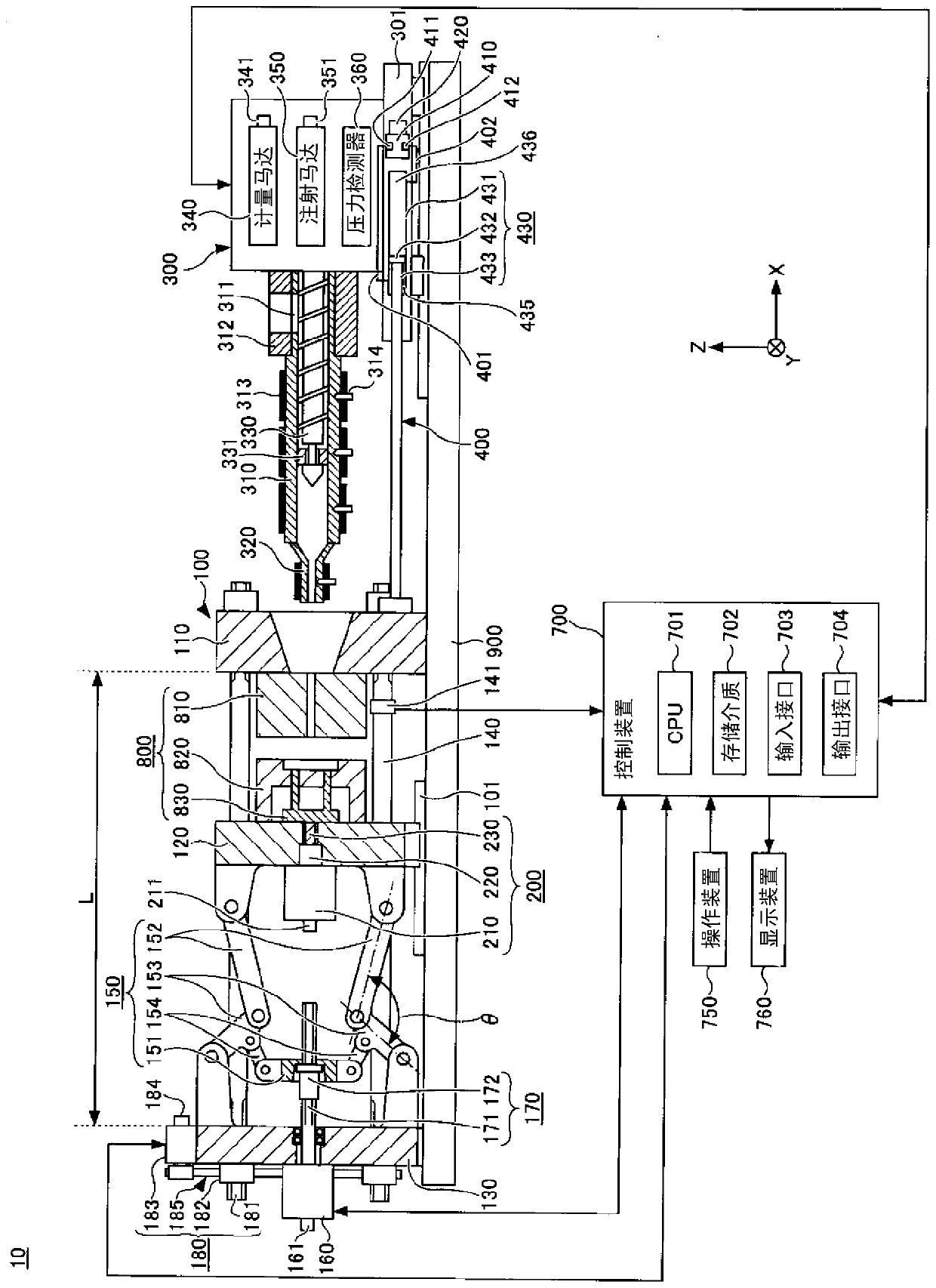
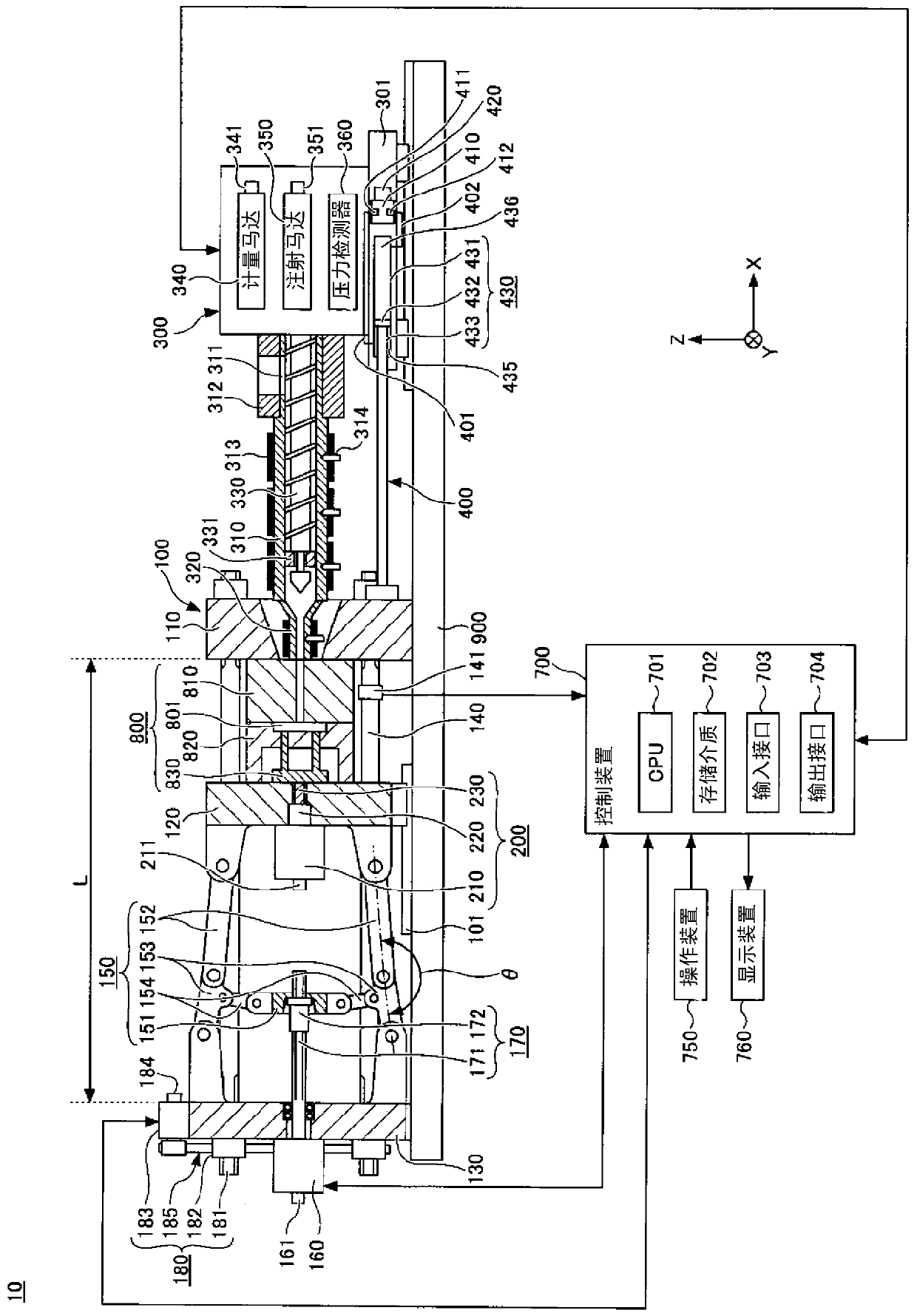
[0032] Hereinafter, modes for implementing the present invention will be described with reference to the drawings. In each of the drawings, the same or corresponding components are assigned the same or corresponding symbols to omit description.

[0033] (injection molding machine)

[0034] figure 1 It is a figure which shows the state at the end of mold opening of the injection molding machine of one embodiment. figure 2 It is a figure which shows the state at the time of mold clamping of the injection molding machine of one embodiment. figure 1 and figure 2 Among them, the X direction, the Y direction, and the Z direction are directions perpendicular to each other. The X direction and the Y direction represent the horizontal direction, and the Z direction represents the vertical direction. When the mold clamping device 100 is a horizontal type, the X direction is the mold opening and closing direction, and the Y direction is the width direction of the injection molding ...


PUM


Abstract

The invention provides an injection molding machine capable of reducing the conflict between an ejector rod and a mold. The injection molding machine includes an ejector rod for ejecting a molding product, a crosshead to which the ejector rod is attached, and a control unit which controls a forward movement or rearward movement of the ejector rod. The control unit includes a storage unit in whichinformation on an attachment of the ejector rod with respect to the crosshead is stored, an acquisition unit which acquires the information on the attachment of the ejector rod with respect to the crosshead, and a collation unit which collates the information stored in the storage unit and the information acquired by the acquisition unit.

Description

technical field [0001] This application claims priority based on Japanese Patent Application No. 2018-068046 filed on March 30, 2018. The entire contents of this Japanese application are incorporated herein by reference. [0002] The invention relates to an injection molding machine. Background technique [0003] The injection molding machine includes a mold clamping device and an injection device. The mold clamping device closes, clamps and opens the mold, and the injection device injects the liquid molding material into the cavity space formed in the mold, and solidifies it while applying a holding pressure to the mold. After the mold clamping device opens the mold, the ejector rod installed in the ejector device passes through the through hole of the mold to eject the movable part in the mold. The cured product of the resin cured in the cavity space is pushed down from the mold by the movable member pushed out (advancing) by the ejector pin, and is recovered as a molde...

Claims


Application Information

Patent Timeline
Patent Type & Authority Applications(China)
IPC IPC(8): B29C45/40B29C45/76
CPCB29C45/4005B29C45/7626B29C2945/76083B29C2945/76244
Inventor 平野智裕北口直树
Owner SUMITOMO HEAVY IND LTD
Why Eureka
Try Eureka