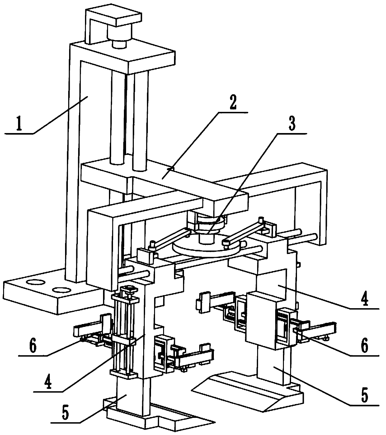
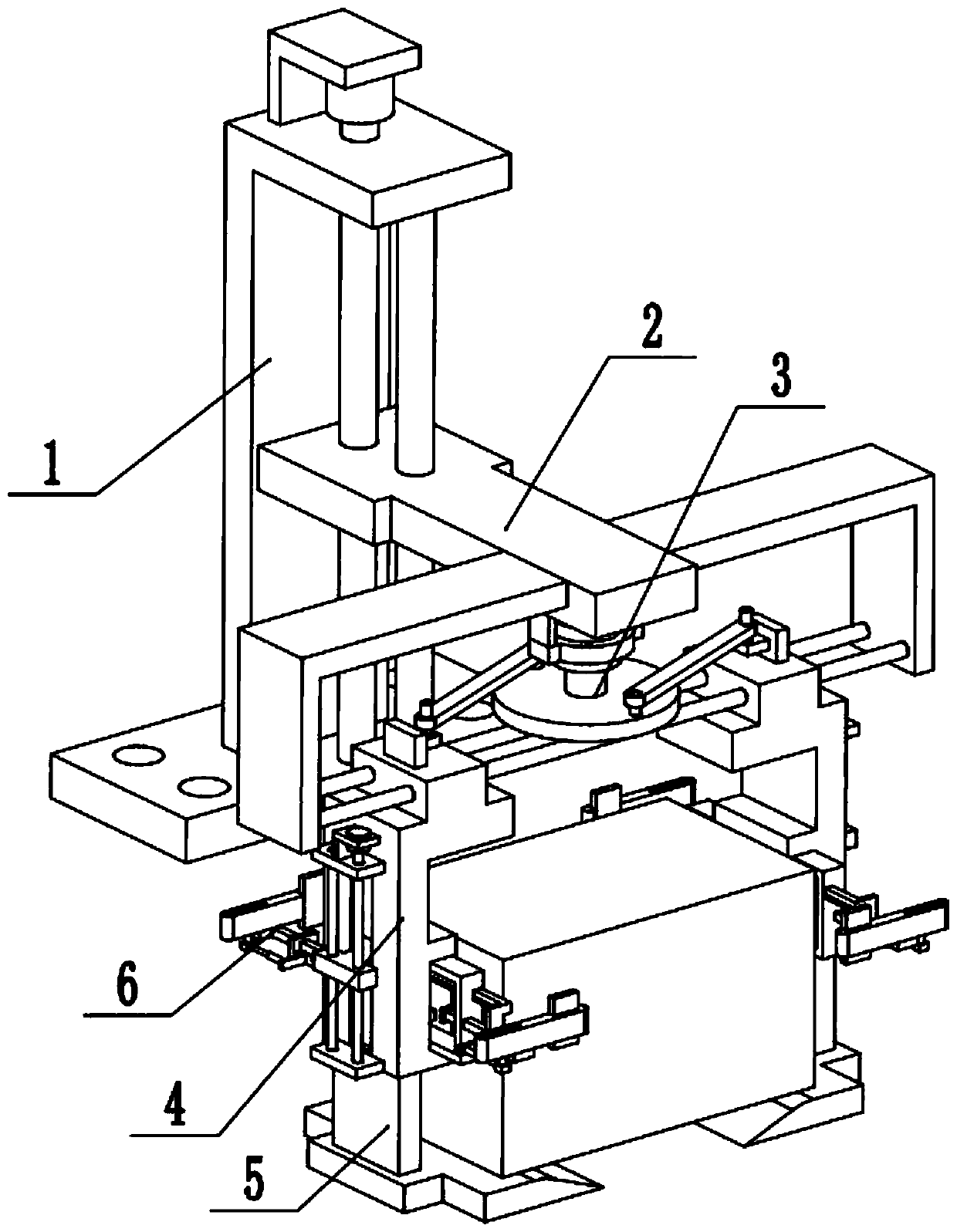
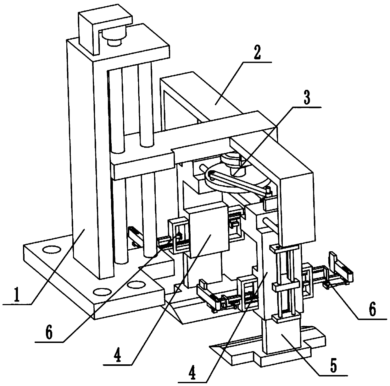
A kind of railway freight hoisting equipment
A technology for hoisting equipment and railway freight transport, applied in the application field of spreaders, can solve problems such as tilt imbalance, cargo sliding collision, damage, etc., and achieve the effects of smooth loading and unloading, ensuring smoothness and high safety factor
- Summary
- Abstract
- Description
- Claims
- Application Information
AI Technical Summary
Problems solved by technology
Method used
Image
Examples
specific Embodiment approach 1
[0033] Combine below Figure 1-14Description of this embodiment, a railway freight hoisting equipment, including a frame 1, a height adjustment frame 2, a width adjustment frame 3, a side frame plate assembly 4, a telescopic pallet assembly 5 and an auxiliary clamping assembly 6, the height adjustment The frame 2 is connected to the frame 1, the middle end of the width adjustment frame 3 is fixedly connected to the front end of the height adjustment frame 2, the left and right ends of the width adjustment frame 3 are respectively slidingly fitted and connected to the two ends of the height adjustment frame 2, and the side frame plate There are two components 4, two side frame components 4 are symmetrically fixedly connected to the left and right ends of the width adjustment frame 3, two telescopic pallet components 5 are provided, and the two telescopic pallet components 5 are symmetrically arranged on both sides Outside the lower end of the shelf assembly 4 , there are two au...
specific Embodiment approach 2
[0035] Combine below Figure 1-14 To illustrate this embodiment, the frame 1 includes a fixed base 1-1, an L-shaped support frame 1-2, a motor I1-3, a motor frame I1-4, a screw 1-5 and a guide rod 1-6; L The L-shaped support frame 1-2 is fixedly connected to the fixed base 1-1, the motor Ⅰ1-3 is fixedly connected to the upper end of the L-shaped support frame 1-2 through the motor frame Ⅰ1-4, and the output shaft of the motor Ⅰ1-3 passes through the coupling Connect the lead screw 1-5, the two ends of the lead screw 1-5 are respectively connected to the upper end of the L-shaped support frame 1-2 and the fixed base 1-1 through bearings with seats, and the two ends of the guide rod 1-6 are respectively fixed Connect the upper end of the L-shaped support frame 1-2 with the fixed base 1-1. When the frame 1 is in use, the bottom of the fixed base 1-1 is provided with a plurality of fixing through holes, so the device can be fixed at the corresponding position through the fixed ba...
specific Embodiment approach 3
[0037] Combine below Figure 1-14 To illustrate this embodiment, the height adjustment frame 2 includes a height adjustment plate 2-1, an L-shaped side support 2-2 and a round rod 2-3; the L-shaped side support 2-2 is provided with two, two L-shaped The side bracket 2-2 is symmetrically fixedly connected to the front end of the height adjustment plate 2-1, and two round rods 2-3 are fixedly connected between the two L-shaped side brackets 2-2; the height adjustment plate 2-1 is connected by sliding fit On the guide rod 1-6, the height adjustment plate 2-1 is screwed on the leading screw 1-5. When the height adjustment frame 2 is in use, when the motor I1-3 drives the lead screw 1-5 to rotate, the height adjustment plate 2-1 and the lead screw 1-5 are threaded to generate relative displacement, and the lead screw 1-5 drives the height The adjustment plate 2-1 moves up and down, and the height adjustment plate 2-1 drives the width adjustment frame 3, two side frame plate compon...
PUM
 Abstract
Description
Claims
Application Information
 - R&D
- Intellectual Property
- Life Sciences
- Materials
- Tech Scout
- Unparalleled Data Quality
- Higher Quality Content
- 60% Fewer Hallucinations
Browse by: Latest US Patents, China's latest patents, Technical Efficacy Thesaurus, Application Domain, Technology Topic, Popular Technical Reports.
© 2025 PatSnap. All rights reserved.Legal|Privacy policy|Modern Slavery Act Transparency Statement|Sitemap|About US| Contact US: help@patsnap.com


