Rail freight hoisting equipment

A technology for hoisting equipment and railway freight transport, applied in the application field of spreaders, can solve problems such as tilt imbalance, cargo sliding collision, damage, etc., and achieve the effects of smooth loading and unloading, ensuring smoothness and high safety factor

Active Publication Date: 2019-10-11
ZHENGZHOU RAILWAY VOCATIONAL & TECH COLLEGE
View PDF11 Cites 19 Cited by
  • Summary
  • Abstract
  • Description
  • Claims
  • Application Information

AI Technical Summary

Problems solved by technology

However, when the device is hoisted, the center of gravity of the container is adjusted according to the direction in which the container is dumped, that is, the container will be tilted and unbalanced due to the unstable center of gravity at the initial stage of hoisting. Cargo will still be damaged due to sliding and collision due to unstable center of gravity

Method used


Image

  • Rail freight hoisting equipment
  • Rail freight hoisting equipment
  • Rail freight hoisting equipment

Examples


specific Embodiment approach 1

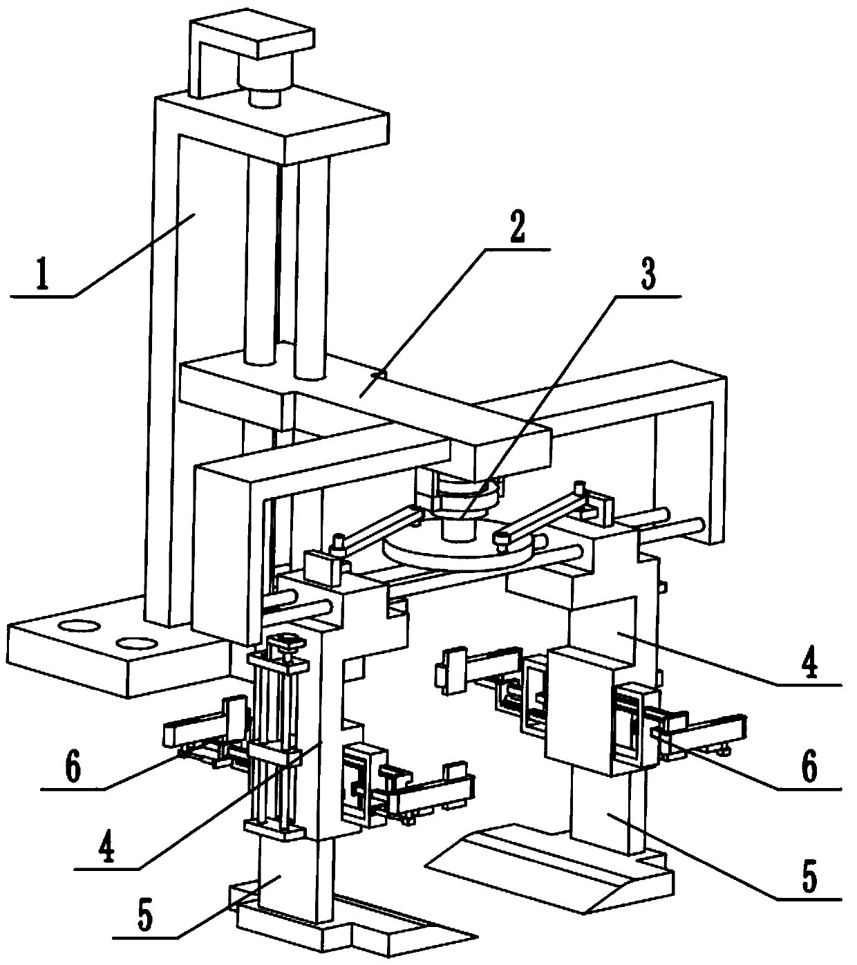
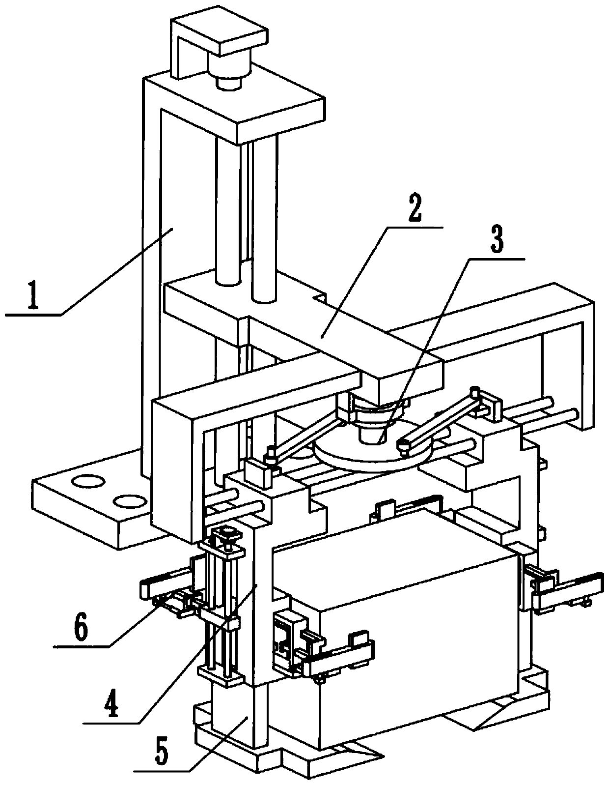
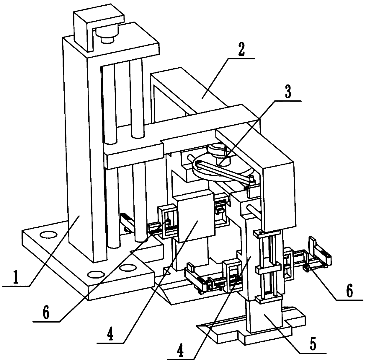
[0033] Combine below Figure 1-14Description of this embodiment, a railway freight hoisting equipment, including a frame 1, a height adjustment frame 2, a width adjustment frame 3, a side frame plate assembly 4, a telescopic pallet assembly 5 and an auxiliary clamping assembly 6, the height adjustment The frame 2 is connected to the frame 1, the middle end of the width adjustment frame 3 is fixedly connected to the front end of the height adjustment frame 2, the left and right ends of the width adjustment frame 3 are respectively slidingly fitted and connected to the two ends of the height adjustment frame 2, and the side frame plate There are two components 4, two side frame components 4 are symmetrically fixedly connected to the left and right ends of the width adjustment frame 3, two telescopic pallet components 5 are provided, and the two telescopic pallet components 5 are symmetrically arranged on both sides Outside the lower end of the shelf assembly 4 , there are two au...

specific Embodiment approach 2

[0035] Combine below Figure 1-14 To illustrate this embodiment, the frame 1 includes a fixed base 1-1, an L-shaped support frame 1-2, a motor I1-3, a motor frame I1-4, a screw 1-5 and a guide rod 1-6; L The L-shaped support frame 1-2 is fixedly connected to the fixed base 1-1, the motor Ⅰ1-3 is fixedly connected to the upper end of the L-shaped support frame 1-2 through the motor frame Ⅰ1-4, and the output shaft of the motor Ⅰ1-3 passes through the coupling Connect the lead screw 1-5, the two ends of the lead screw 1-5 are respectively connected to the upper end of the L-shaped support frame 1-2 and the fixed base 1-1 through bearings with seats, and the two ends of the guide rod 1-6 are respectively fixed Connect the upper end of the L-shaped support frame 1-2 with the fixed base 1-1. When the frame 1 is in use, the bottom of the fixed base 1-1 is provided with a plurality of fixing through holes, so the device can be fixed at the corresponding position through the fixed ba...

specific Embodiment approach 3

[0037] Combine below Figure 1-14 To illustrate this embodiment, the height adjustment frame 2 includes a height adjustment plate 2-1, an L-shaped side support 2-2 and a round rod 2-3; the L-shaped side support 2-2 is provided with two, two L-shaped The side bracket 2-2 is symmetrically fixedly connected to the front end of the height adjustment plate 2-1, and two round rods 2-3 are fixedly connected between the two L-shaped side brackets 2-2; the height adjustment plate 2-1 is connected by sliding fit On the guide rod 1-6, the height adjustment plate 2-1 is screwed on the leading screw 1-5. When the height adjustment frame 2 is in use, when the motor I1-3 drives the lead screw 1-5 to rotate, the height adjustment plate 2-1 and the lead screw 1-5 are threaded to generate relative displacement, and the lead screw 1-5 drives the height The adjustment plate 2-1 moves up and down, and the height adjustment plate 2-1 drives the width adjustment frame 3, two side frame plate compon...


PUM


Abstract

The invention relates to the technical field of lifting appliance application, in particular to rail freight hoisting equipment. The rail freight hoisting equipment comprises a rack, a height adjusting frame, a width adjusting frame, side frame plate assemblies, telescopic supporting plate assemblies and an auxiliary clamping assembly. The rail freight hoisting equipment has the advantages that when a container is hoisted, offset is avoided, and the rail freight hoisting equipment is suitable for long-distance transportation; and the upper face, the lower face, the left face, the right face, the front face and the back face of the container can be clamped, shaking is avoided, loading and unloading are stable, and the safety coefficient is high. The height adjusting frame is connected to the rack, and the middle end of the height adjusting frame is fixedly connected to the front end of the height adjusting frame. The left end and the right end of the width adjusting frame are in slidingfit connection with the two ends of the height adjusting frame correspondingly. Two side frame plate assemblies are arranged and symmetrically and fixedly connected to the left end and the right endof the width adjusting frame. Two telescopic supporting plate assemblies are arranged and are symmetrically arranged on the outers sides of the lower ends of the two side frame plate assemblies.

Description

technical field [0001] The invention relates to the technical field of spreader application, more specifically to a railway freight lifting equipment. Background technique [0002] The existing patent number is CN201720404338.2 for a railway freight container spreader. This utility model discloses a railway freight container spreader, which includes a main frame and an adjustment frame. The main frame is fixedly installed with transverse fasteners and Vertical fasteners, the bottom four corners of the main body frame are all provided with re-pin mechanisms, the four side outer walls of the main body frame are fixedly equipped with positioning plates, and the inner sides of the four corners of the main body frame are fixedly installed with rope fixing blocks, The rope fixing block is connected with a hoisting rope, and the adjustment frame is connected with the main body frame through the hoisting rope. The upper left and right ends of the adjustment frame are fixedly install...

Claims


Application Information

Patent Timeline
Patent Type & Authority Applications(China)
IPC IPC(8): B66C1/30B66C1/42B66C13/06
CPCB66C1/30B66C1/42B66C13/06
Inventor 原方方崔琬茹李海龙帖鹏飞马芳李亚赵明丽李文举
Owner ZHENGZHOU RAILWAY VOCATIONAL & TECH COLLEGE
Why Eureka
Try Eureka