Bidirectional initiating explosive device plug connection state identification method

A state identification and plug connection technology is applied in the field of two-way pyrotechnic plug connection status recognition, which can solve the problem that missile mounting operators cannot check the connection status of the missile-borne computer plug and the pyrotechnic plug.

Inactive Publication Date: 2019-10-11
JIANGXI HONGDU AVIATION IND GRP
View PDF9 Cites 1 Cited by
  • Summary
  • Abstract
  • Description
  • Claims
  • Application Information

AI Technical Summary

Problems solved by technology

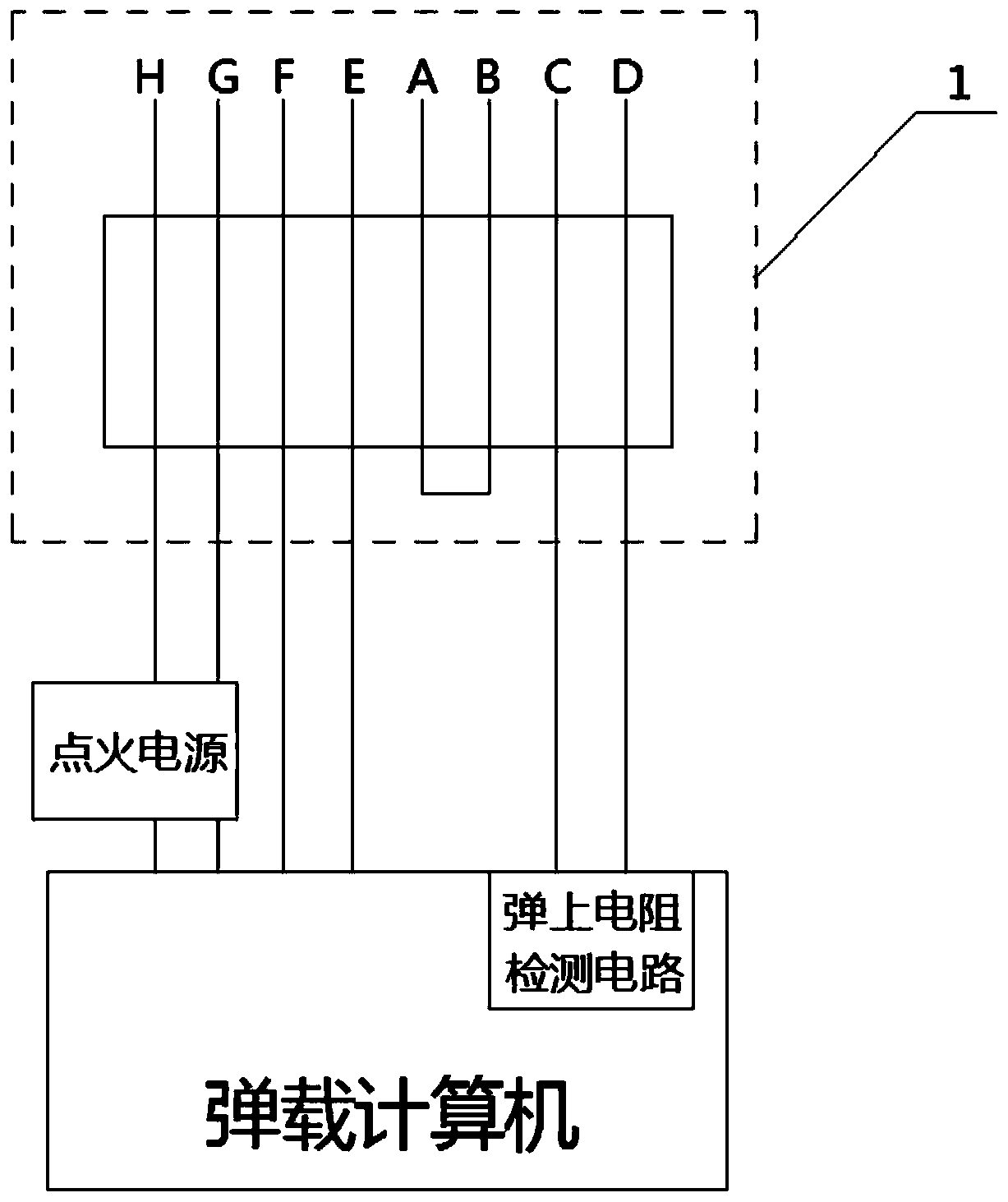
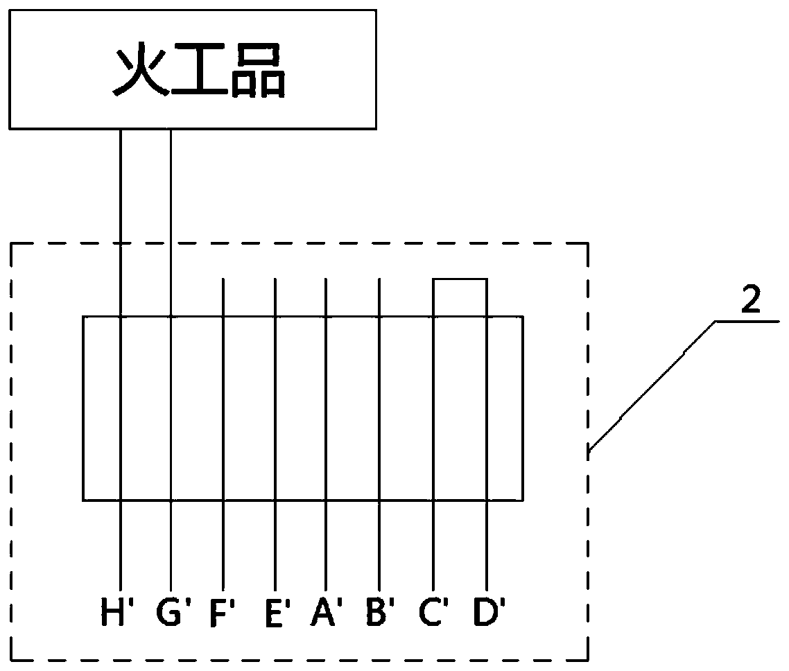
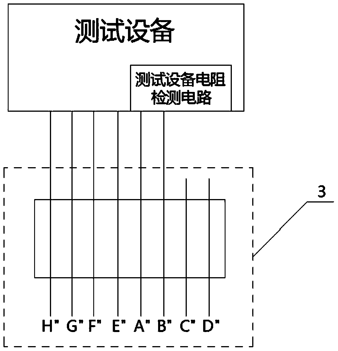
[0003] In order to overcome the deficiencies in the background technology, the present invention discloses a method for identifying the connection state of a two-way pyrotechnic plug, including a bomb-borne computer plug, a pyrotechnic plug, and a test equipment plug; the computer-loaded plug, pyrotechnic plug, On the basis of the original pins, the test equipment plug has four additional pins; among them, the bomb-borne computer plug has added short-circuit pins A and B of the bomb-borne computer plug and pins C and D for resistance detection on the bomb; The product plug adds the open circuit pins A', B' of the pyrotechnic product plug and the short circuit pin C', D' of the pyrotechnic product; the test equipment plug adds the test equipment resistance detection pin A", B" and the test equipment plug Open circuit pins C", D"; In addition, the bomb-on-board r

Method used


Image

  • Bidirectional initiating explosive device plug connection state identification method
  • Bidirectional initiating explosive device plug connection state identification method
  • Bidirectional initiating explosive device plug connection state identification method

Examples


Embodiment Construction

[0018] The present invention can be explained in detail through the following examples, and the purpose of disclosing the present invention is to protect all technical improvements within the scope of the present invention.

[0019] A method for identifying the connection state of a two-way pyrotechnic plug, comprising a bomb-borne computer plug 1, a pyrotechnic plug 2, and a test equipment plug 3; the bomb-borne computer plug 1 includes communication pins E and F of the bomb-borne computer plug. Carry computer plug ignition pins G, H; the pyrotechnic plug 2 includes pyrotechnic plug communication pins E', F', pyrotechnic plug ignition pins G', H', pyrotechnic plug communication pins The pins E', F' are suspended; the test equipment plug 3 includes the test equipment plug communication pins E", F", and the test equipment plug ignition pins G", H"; it is characterized in that: 1. The short-circuit pins A and B of the bomb-borne computer plug and the resistance detection pins C ...


PUM


Abstract

The invention discloses a bidirectional initiating explosive device plug connection state identification method comprising a missile-borne computer plug, an initiating explosive device plug and a testequipment plug; based on original pins, four pins are additionally arranged on each of the missile-borne computer plug, the initiating explosive device plug and the test equipment plug; furthermore,a missile resistance detection circuit is added to a missile-borne computer connected with the missile-borne computer plug, and a test equipment resistance detection circuit is added to test equipmentconnected with the test equipment plug; the missile resistance detection circuit and the test equipment resistance detection circuit are matched with the four additionally-arranged pins of each of the missile-borne computer plug, the initiating explosive device plug and the test equipment plug, and thus the connection state of the bidirectional initiating explosive device plug can be accurately detected; therefore, the problem that after the aircraft loading operation of an air-to-air missile is completed, missile mounting operation personnel and a carrier aircraft pilot cannot check the connection states of the missile-borne computer plug and the initiating explosive device plug is solved, so that the risk of missed connection of the missile-borne computer plug and the initiating explosive device plug is thoroughly avoided.

Description

technical field [0001] The invention relates to the field of air-to-air missile testing technology and missile-machine communication technology, in particular to a method for identifying the connection state of a two-way pyrotechnic product plug. Background technique [0002] The air-to-air missile loaded with pyrotechnics is called a full-bore bomb. When the full-bore bomb is in the test and storage state, it is dangerous. The physical isolation between the artifact and the missile-borne computer or testing equipment; and before the air-to-air missile is installed, the missile-borne computer plug must be connected to the pyrotechnic product plug before the installation operation can be carried out; in order to prevent the occurrence of the bomb-borne computer plug and If the pyrotechnic plug is not connected, a red warning sign will be hung at the pyrotechnic plug before installation, with the warning words "connect and remove before mounting" written on it, which is used t...

Claims


Application Information

Patent Timeline
IPC IPC(8): G01R31/04F42B35/00
CPCF42B35/00G01R31/69
Inventor 鞠新星胜永民艾龙龙高祥李明章李永强杜文涛童琴陈龙张洪宇彭志翔周炫曹宏友朱倩倩刘毅
Owner JIANGXI HONGDU AVIATION IND GRP
Why Eureka
Try Eureka