Supercharge Your Innovation With Domain-Expert AI Agents!

Pushing and pulling rod of wire clamping device

A wire clamp and pull rod technology, which is applied in the direction of overhead lines/cable equipment, etc., can solve the problems such as the difficulty in recycling the wire clamp, and achieve the effect of convenient clamping and recycling

Pending Publication Date: 2019-10-11
GUANGDONG POWER GRID CO LTD +1
View PDF0 Cites 0 Cited by
  • Summary
  • Abstract
  • Description
  • Claims
  • Application Information

AI Technical Summary

Problems solved by technology

[0003] In order to overcome the defect of the difficult recovery of the wire clamp described in the prior art, the present invention provides a wire clamp push-pull rod, which can not only push the wire clamp out for a long distance, but also conveniently recover the wire clamp

Method used


Image

  • Pushing and pulling rod of wire clamping device
  • Pushing and pulling rod of wire clamping device

Examples


Embodiment 1

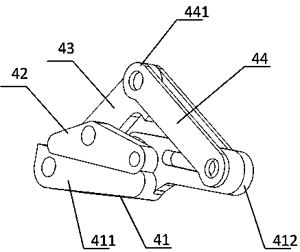
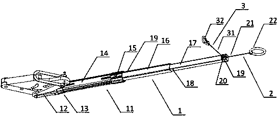
[0032] A wire clamp push-pull rod, such as figure 2 As shown, it includes a telescopic push rod 1 for pushing out the wire gripper, and a pulling part 2 for drawing the wire gripper closer. The telescopic push rod 1 includes a telescopic sleeve 11 and a connecting part 12. The telescopic sleeve 11 includes a large To the first sleeve pipe 14, the second sleeve pipe 16 and the third sleeve pipe 17 which are nested in turn, the second sleeve pipe 16 protrudes from one end of the first sleeve pipe 14, and the other end of the first sleeve pipe 14 is connected by The pipe 13 is fixedly connected with the connection part 12, the connection part 12 is a U-shaped part 12, and the U-shaped part 12 includes two opposite legs, and the two opposite legs are used to clamp the bolted end 441 of the pull plate and connect with the pull plate. The bolted end 441 is detachably bolted.

[0033] After the second sleeve 16 stretches out, the wall near one end of the first sleeve 14 is provided...


PUM


Abstract

The invention discloses a pushing and pulling rod of a wire clamping device. The pushing and pulling rod of a wire clamping device comprises a telescopic push rod for pushing out a wire clamping device and a pulling part for getting close to the wire clamping device, wherein the telescopic push rod comprises a telescopic sleeve pipe and a connecting part arranged at one end of the telescopic sleeve pipe, and the connecting part is used for being detachably connected with a pulling plate of the wire clamping device; the pulling part comprises a pull rope and a pull ring, one end of the pull rope is used for being detachably connected with a lower clamping plate of the wire clamping device, and the other end of the pull rope is connected with the pull ring. The pushing and pulling rod of thewire clamping device can push the wire clamping device out for a long distance and can conveniently get the wire clamping device back.

Description

technical field [0001] The invention relates to the field of electric power construction tools, and more specifically, to a push-pull rod of a wire gripper. Background technique [0002] At present, the push-out distance of the cable clamp is limited. In many cases, the staff needs to push the cable clamp farther, and it can be recycled after use. Many workers on the pole just push the wire clamp to the farthest with their hands, but it is difficult to recover; there are also many workers who use sticks to push the wire clamp for a long distance, making recovery even more difficult. There is an urgent need to design a tool that can not only push the wire clamp out a long distance, but also easily recover the wire clamp. Contents of the invention [0003] In order to overcome the defect of the difficult recovery of the wire clamp described in the prior art, the present invention provides a wire clamp push-pull rod, which can not only push the wire clamp out for a long dist...

Claims


Application Information

Patent Timeline
Patent Type & Authority Applications(China)
IPC IPC(8): H02G1/02H02G1/04
CPCH02G1/02H02G1/04
Inventor 苏欢欢范伟波黎嘉达谭永安张博韦颖康叶露黄章娉温振宇
Owner GUANGDONG POWER GRID CO LTD
Features
  • R&D
  • Intellectual Property
  • Life Sciences
  • Materials
  • Tech Scout
  • Unparalleled Data Quality
  • Higher Quality Content
  • 60% Fewer Hallucinations
Learn More