
Take-off and landing device of unmanned aerial vehicle and take-off and landing method thereof

A technology of landing gear and unmanned aerial vehicles, applied in the field of unmanned aerial vehicles, can solve problems such as insufficient endurance and limitation of endurance, and achieve the effect of improving endurance and docking ability

Active Publication Date: 2019-10-15
HANGZHOU DIANZI UNIV
View PDF6 Cites 2 Cited by
  • Summary
  • Abstract
  • Description
  • Claims
  • Application Information

AI Technical Summary

Problems solved by technology

UAVs have the advantages of simple structure, flexible maneuverability, etc., but their insufficient battery life has become their biggest weakness
Since most UAVs are powered by batteries, the battery life is limited by battery technology.

Method used


Image

  • Take-off and landing device of unmanned aerial vehicle and take-off and landing method thereof
  • Take-off and landing device of unmanned aerial vehicle and take-off and landing method thereof
  • Take-off and landing device of unmanned aerial vehicle and take-off and landing method thereof

Examples


Embodiment 1

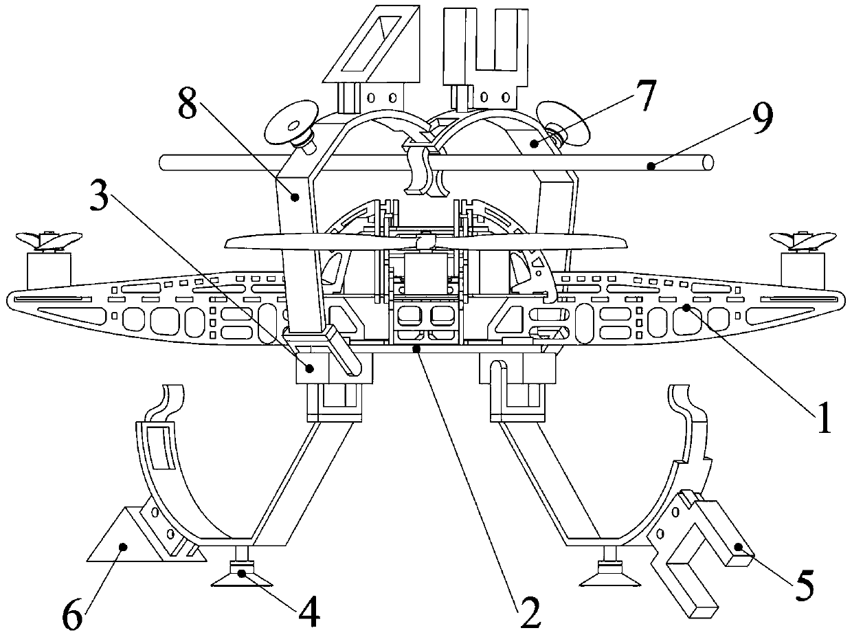
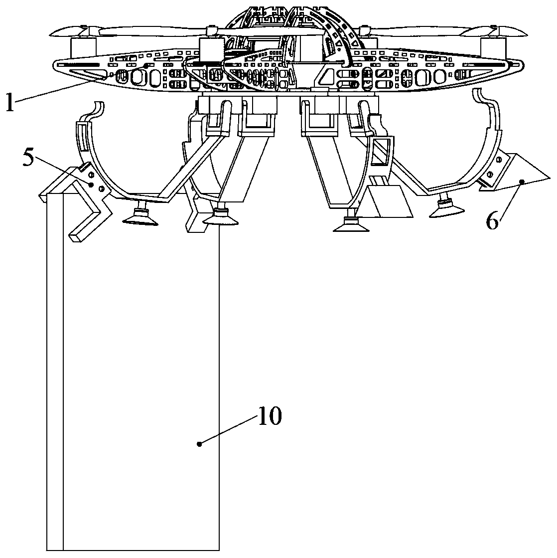
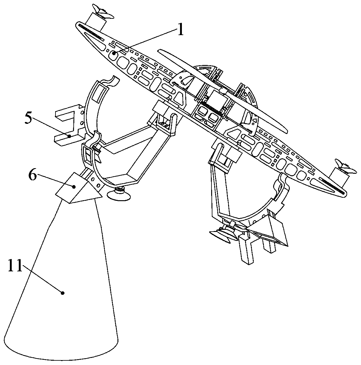
[0050] Such as figure 1 , 2Shown in and 3, a kind of unmanned aerial vehicle landing gear, comprises unmanned aerial vehicle main body 1, flip type landing gear and controller. The main body 1 of the UAV is a conventional four-axis UAV, with four support arms spread out in a cross shape, and a propeller and a drive motor are installed at the end of each support arm. The reversing landing gear includes a base plate 2, a reversing steering gear 3, a lifting suction cup 4, a board top resting block 5, a cone top resting block 6 and a reversing landing assembly. The reversing landing assembly includes a first reversing arm 7 and a second reversing arm 8 . The base plate 2 is fixed on the bottom of the main body of the drone. The materials of the first turning arm 7 and the second turning arm 8 are both rubber.

[0051] Such as figure 1 and 4 As shown, the first turning arm 7 includes a first connecting plate 7-1, a first lift floor 7-2, a first transition plate 7-3 and a fir...

Embodiment 2

[0083] A landing gear for unmanned aerial vehicles, the difference from Embodiment 1 is:

[0084] The two top resting blocks 5 are respectively fixed to the outer surfaces of the first transition plate 7-3 of the first turning arm 7 in the two turning lifting assemblies. The two cone-top resting blocks 6 are respectively fixed to the outer surfaces of the second transition plate 8-3 of the second turning arm 8 in the two turning lifting and landing assemblies.


PUM


Abstract

The invention discloses a take-off and landing device of an unmanned aerial vehicle and a take-off and landing method thereof. The unmanned aerial vehicle has the advantages of simple structure, flexibility and the like, but cruising ability insufficiency becomes the greatest weakness. The take-off and landing device comprises a substrate, an overturning steering engine, a plate roof docking block, a cone roof docking block and an overturning take-off and landing assembly, wherein the substrate is fixed to the bottom of a main body of the unmanned aerial vehicle; the overturning take-off and landing assembly comprises a first overturning arm and a second overturning arm; the first overturning arm comprises a first connecting plate, a first take-off and landing base plate, a first transition plate and a first attaching single claw which are connected in sequence; and the second overturning arm comprises a second connecting plate, a second take-off and landing base plate, a second transition plate, a groove through plate and a first attaching single claw which are connected in sequence. The unmanned aerial vehicle can dock at a relatively high position, and the unmanned aerial vehicle also can preferably perform tasks such as detection, search and rescue in a docking condition, so that the cruising ability of the unmanned aerial vehicle is improved.

Description

technical field [0001] The invention belongs to the technical field of unmanned aerial vehicles, and in particular relates to an unmanned aerial vehicle lifting device and a lifting and landing method thereof. Background technique [0002] In recent years, with the reduction of manufacturing costs and the development of technology, drones have rapidly entered the mass consumer market. The application scenarios of drones are very extensive, such as aerial photography, agricultural plant protection, surveying and mapping, reconnaissance and monitoring, disaster rescue, power inspection and other fields. UAVs have advantages such as simple structure and flexible maneuverability, but their insufficient endurance has become their biggest weakness. Since most UAVs are powered by batteries, the battery life is limited by battery technology. Therefore, how to reduce energy consumption has become the main research direction of prolonging the endurance of UAVs. Contents of the inv...

Claims


Application Information

Patent Timeline
IPC IPC(8): B64C25/10B64C25/32
CPCB64C25/10B64C25/32B64U70/00B64U10/10
Inventor 许明章佳奇陈国金
Owner HANGZHOU DIANZI UNIV
Learn More