Supercharge Your Innovation With Domain-Expert AI Agents!

Catenary grounding device fall restriction apparatus and method of use

A technology of grounding device and catenary, which is applied in the field of contact heads, and can solve problems such as contact head 10 dropping

Inactive Publication Date: 2019-10-18
DUBUIS & CIE
View PDF6 Cites 0 Cited by
  • Summary
  • Abstract
  • Description
  • Claims
  • Application Information

AI Technical Summary

Problems solved by technology

In the case of high current, the electromagnetic force caused by the current may force the contact 10 out of the suspension engagement with the catenary 12, causing the contact 10 to fall
Other conditions such as wind may cause the contact head 10 to fall from the catenary 12

Method used


Image

  • Catenary grounding device fall restriction apparatus and method of use
  • Catenary grounding device fall restriction apparatus and method of use
  • Catenary grounding device fall restriction apparatus and method of use

Examples


Embodiment Construction

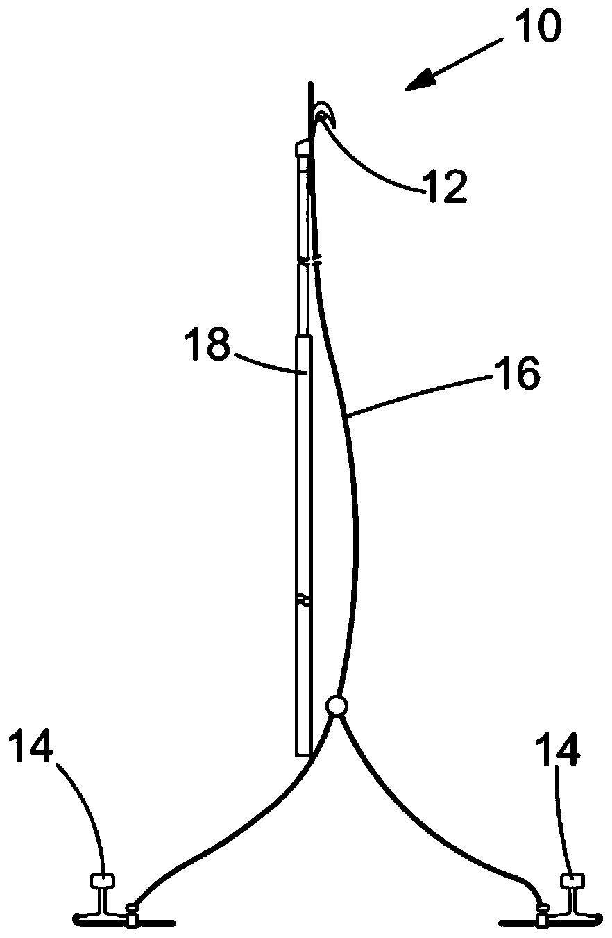
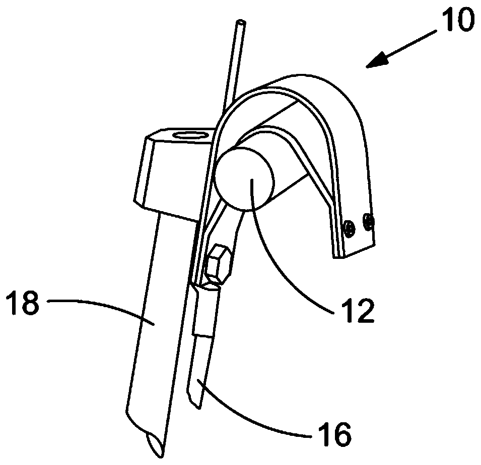
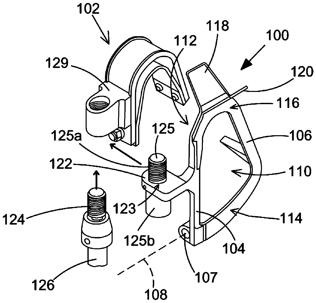
[0032] image 3 Shown is an apparatus 100 for suppressing accidental fall from a catenary in use of a contact head 102 of a catenary grounding device, wherein the contact head 102 may be configured substantially similarly to the context herein Contact heads of the type described in EP0810691B1 mentioned in the technical part.

[0033] Figure 3 to Figure 5 It is shown that the device 100 has a first arm 104 and a second arm 106 which are pivotally coupled relative to each other about an axis 108 at a pivot connection 107 . exist Figure 3 to Figure 5 In the figure, the first arm 104 and the second arm 106 are shown relative to each other in a closed configuration (closed configuration), in which the first arm 104 and the second arm 106 cooperate to define a circle in use. The channel 110 of the catenary in.

[0034] image 3 and Figure 6c It is shown that although first arm 104 does not define a lower portion of channel 110 for limiting movement of device 100 with an up...


PUM


Abstract

Apparatus for restricting a contact head of a catenary grounding device unintentionally falling from a catenary in use that is connectable to a said contact head, and method of use. Apparatus formingpart of a contact head of a catenary grounding device for restricting the contact head unintentionally falling from a catenary in use, and method of use.

Description

technical field [0001] The present application relates to devices for limiting unintentional falling of contacts of catenary grounding devices from a catenary in use, contacts provided with such devices and methods of their use . Background technique [0002] EP0810691B1 teaches a contact for short-circuiting a catenary supplying current to a railway train. During maintenance of such a catenary, it is important to short circuit the catenary by electrically coupling the catenary to ground. this is in figure 1 is shown in , where the contact head 10 is suspended from a catenary 12, and the catenary 12 is coupled by a wire arrangement 16 to a rail 14 in contact with the ground. Rod 18 is used to lift contact head 10 into contact with catenary 12 . The close-up of the contact head 10 suspended on the catenary 12 is in figure 2 is shown in , where the conductive member of the contact head 10 electrically couples the catenary 12 to the wire arrangement 16 . In the case of h...

Claims


Application Information

Patent Timeline
IPC IPC(8): B60M1/02
CPCB60M1/02H01R11/14H02G1/02H01R4/66H01R43/00H02G7/22
Inventor 纪尧姆·吉德尔
Owner DUBUIS & CIE
Features
  • R&D
  • Intellectual Property
  • Life Sciences
  • Materials
  • Tech Scout
  • Unparalleled Data Quality
  • Higher Quality Content
  • 60% Fewer Hallucinations
Learn More