Tunnel road safety structure based on drainage system

A drainage system and safety structure technology, applied in drainage, safety devices, mining equipment, etc., can solve problems such as collisions on inner walls, rear-end collisions, traffic accidents, etc., and achieve the effect of increasing safety

Active Publication Date: 2019-10-22
义乌市高洋建筑工程有限公司
View PDF10 Cites 0 Cited by
  • Summary
  • Abstract
  • Description
  • Claims
  • Application Information

AI Technical Summary

Problems solved by technology

Once the vehicle is driving towards the inner wall of the tunnel due to fatigue driving or lighting, it is easy to hit the inner wall because the direction is not adjusted in time, especially for drivers who are fatigued, the vehicle is always in a stable driving state, which is particularly easy Fatigue driving, once this happens, there is generally no warning in the prior art, and the vehicle will slowly approach the inner wall. Sometimes it is difficult to notice the rear vehicle when driving in a dangerous area, and the rear If the vehicle is following closely at this time, it is difficult to find that the vehicle in front has deviated from its route, and it will often choose to continue following the vehicle. However, once the vehicle in front hits the side wall, the vehicle behind has no time to react at this time. And then cause rear-end collision, causing serious traffic accident

Method used


Image

  • Tunnel road safety structure based on drainage system
  • Tunnel road safety structure based on drainage system
  • Tunnel road safety structure based on drainage system

Examples


Embodiment Construction

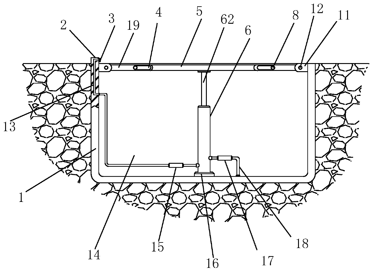
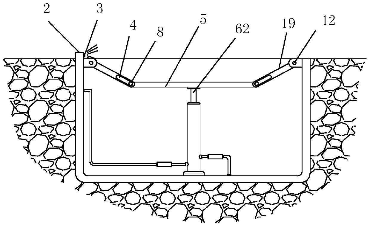
[0018] Such as figure 1 and Figure 4 As shown, the tunnel road safety structure based on the drainage system includes embedded parts 1 arranged on both sides of the tunnel. The upper end surface of the embedded part 1 is flush with the upper end surface of the tunnel ground. A drainage cavity 14 with an open top, and more than one composite protection rod is equidistantly arranged at the top opening end of the drainage chamber 14, and the composite protection rods are arranged equidistantly along the length direction of the embedded part 1, and the two sides of each composite protection rod They are all hinged on the connecting ear 11 on the inner wall of the drainage cavity. A buffer support 6 is provided at the bottom of each composite protection rod. The buffer support 6 lifts up the composite protection rod and makes the composite protection rod parallel to the horizontal plane.

[0019] In this embodiment, the composite protective rod includes two connecting rods 19 and...


PUM


Abstract

The invention discloses a tunnel road safety structure based on a drainage system. The tunnel road safety structure comprises pre-buried parts distributed on the two sides of a tunnel. The upper end faces of the pre-buried parts are flushed with the upper end face of the road surface of the tunnel. A drainage cavity with an opening formed in the top is formed in each pre-buried part. One or more composite protection rod is arranged at the top open end of each drainage cavity at equal distance. The composite protection rods are distributed in the length direction of the pre-buried parts at equal distance. The two sides of each composite protection rod are hinged to connecting lugs on the inner wall of the corresponding drainage cavity. A buffer supporting part is arranged at the bottom of each composite protection rod. The composite protection rods are jacked by the buffer supporting rods and can be parallel to the horizontal plane. According to the tunnel road safety structure, the space in the tunnel cannot be occupied, the tunnel road safety structure can be used as the drainage system and can also be used for vehicle safety protection and warning for rear vehicles, vehicles areprevented from impacting on the inner wall face of the tunnel, and the rear-end accidents of the rear vehicles are reduced.

Description

technical field [0001] The invention relates to a safety structure, in particular to a tunnel road safety structure based on a drainage system. Background technique [0002] There are drains on both sides of the road in the tunnel, these drains are used to drain the water in the tunnel, and the drains are set close to the inner wall of the tunnel, very close to the inner wall. Once the vehicle is driving towards the inner wall of the tunnel due to fatigue driving or lighting, it is easy to hit the inner wall because the direction is not adjusted in time, especially for drivers who are fatigued, the vehicle is always in a stable driving state, which is particularly easy Fatigue driving, once this happens, there is generally no warning in the prior art, and the vehicle will slowly approach the inner wall. Sometimes it is difficult to notice the rear vehicle when driving in a dangerous area, and the rear If the vehicle is following closely at this time, it is difficult to find...

Claims


Application Information

Patent Timeline
IPC IPC(8): E21F11/00E21F16/02
CPCE21F11/00E21F16/02
Inventor 张根民
Owner 义乌市高洋建筑工程有限公司
Why Eureka
Try Eureka