Multiple anti-motion leg fixing device
A fixed device, multiple technologies, applied in passive exercise equipment, medical science, hospital beds, etc., can solve problems such as inability to achieve rehabilitation training
- Summary
- Abstract
- Description
- Claims
- Application Information
AI Technical Summary
Problems solved by technology
Method used
Image

Examples
specific Embodiment approach 1
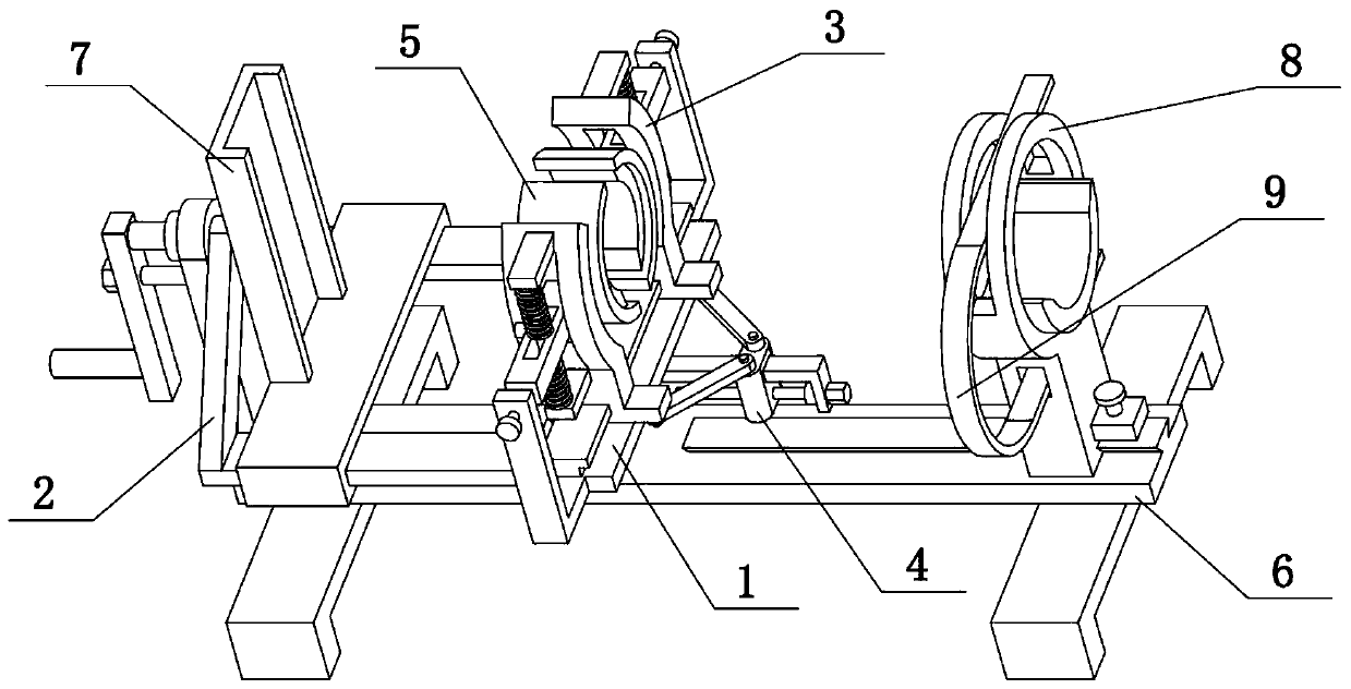
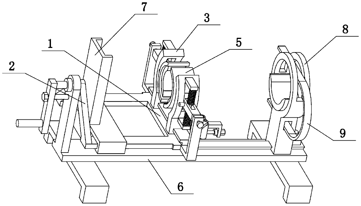
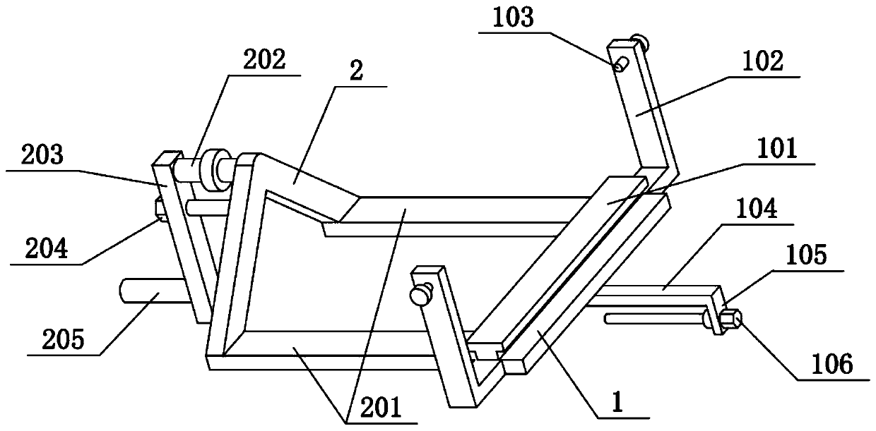
[0037] Combine below Figure 1-12 Describe this embodiment. The present invention relates to orthopedic appliances, more specifically, a multiple anti-movement fixing device for legs, including a horizontal seat 1, a T-shaped slide rail 101, an arc-shaped frame 3, an arc-shaped slide groove 301, and a convex seat 302. , spring sleeve rod 303, splint 5, square column 501, rectangular hole 503 and limit round pin 504, the present invention can clamp and fix the leg, and the leg can be slightly twisted while clamping to achieve the effect of rehabilitation training .
[0038]The upper end of the horizontal seat 1 is provided with a T-shaped slide rail 101, two arc-shaped frames 3 are provided at the front and rear, and two arc-shaped frames 3 are provided with arc-shaped slide grooves 301, and the two arc-shaped frames 3 are respectively slidably connected to the The front and rear ends of the T-shaped slide rail 101, the upper and lower ends of the outer sides of the two arc fr...
specific Embodiment approach 2
[0040] Combine below Figure 1-12 To illustrate this embodiment, the multiple anti-movement fixing device for legs also includes a middle slide rail bar 104, a slider 4 and an equal arm bar 401, the middle slide rail bar 104 is fixedly connected to the lower side of the cross seat 1, and the slide block 4 is slidably connected On the middle slide rail bar 104, the slider 4 can be fixed on the middle slide rail bar 104, two equal arm bars 401 are hingedly connected on the slide block 4, and the other ends of the two equal arm bars 401 are respectively hinged on two The lower end of arc frame 3. The slide block 4 can slide leftward or rightward on the middle slide rail bar 104, and when the slide block 4 slides leftward or rightward, the two arc-shaped frames 3 will be driven close to or far away from the two equal arm bars 401 respectively, and the two arc frames 3 will be adjusted. The spacing between the two arc-shaped frames 3 achieves the effect of clamping the legs.
specific Embodiment approach 3
[0042] Combine below Figure 1-12 To illustrate this embodiment, the multiple anti-movement fixing device for the legs also includes a convex plate 105 and a hand screw 106, the right end of the middle slide rail rod 104 is fixedly connected with the convex plate 105, and the right end of the hand screw 106 is rotatably connected to the convex plate 105, the left end of the hand screw 106 is threaded to cooperate with the slide block 4. When the hand screw 106 rotates on its own axis, it can drive the slider 4 to slide left or right to control the position of the slider 4. When the hand screw 106 does not rotate, the slider 4 is fixed by the thread self-locking effect .
PUM
 Abstract
Description
Claims
Application Information
 - R&D
- Intellectual Property
- Life Sciences
- Materials
- Tech Scout
- Unparalleled Data Quality
- Higher Quality Content
- 60% Fewer Hallucinations
Browse by: Latest US Patents, China's latest patents, Technical Efficacy Thesaurus, Application Domain, Technology Topic, Popular Technical Reports.
© 2025 PatSnap. All rights reserved.Legal|Privacy policy|Modern Slavery Act Transparency Statement|Sitemap|About US| Contact US: help@patsnap.com