Water bag, pressure tank and water purifier
A water purifier and pressure tank technology, applied in water/sewage treatment, water/sewage treatment equipment, water/sludge/sewage treatment, etc. Guarantee effective and ensure the effect of water injection volume
Pending Publication Date: 2019-10-25
FOSHAN SHUNDE MIDEA WATER DISPENSER MFG +1
0 Cites 0 Cited by
AI-Extracted Technical Summary
Problems solved by technology
Usually, there is often air left in the water bag. When the water bag is filled with water, once the air in the ...
Method used
Further, for the base 220, the side of the base 220 facing the water storage cavity 250 is provided with a groove 229, the water channel 221 is located at the bottom of the groove 229, and the groove 229 is connected to the water storage chamber. The cavities 250 are connected to increase the effective water storage volume of the water storage cavity 250 .
Further, in some preferred embodiments, a plurality of second through-flow gaps 245 are also provided on the above-mentioned aqueduct 240, and a plurality of second through-flow notches 245 are arranged at intervals along the extending direction of the aqueduct 240, Furthermore, it is easier for water to circulate between the water guide pipe 240 and the water storage cavity 250 , and the effect of water in and out of the water bag 210 is improved. Wherein, the orientations of at least two of the plurality of second flow notches 245 are different, so that the water in the water storage cavity 250 and the water guide pipe 240 can communicate better.
In the present embodiment, the water channel 221 positioned on the base 220 includes an external water-guiding section 224, a connecting section 225 and an internal water-guiding section 226 connected in sequence, the external water-guiding section 224 communicates with the outside world, and the internal water-guiding section 226 communicates with the water storage cavity 250; the outer water guide section 224 and the connecting section 225 extend in the plane where the bottom of the groove 229 is located, and the air channel 227 is opened on the outer water guiding section 224 and/or the connecting section 225 . The inner water guiding section 226 extends from the bottom of the groove 229 toward the water storage cavity 250 . At this time, when the water channel 221 is formed on the base 220, the thickness of the base 220 itself will not be too large, reducing the material used for the base 220 and saving costs; The side will not be too protruding, and the outer water guide section 224 is prevented from facing the side of the base 220 facing away from the water storage chamber 250, which can reduce the occupation of the inner space of the water purifier 1 by the water bag 210.
It should be noted that, for the above-mentioned water guide pipe 240, the water guide pipe 240 includes a water inlet section 241, a curved section 242 and a water outlet section 243 connected in sequence, the water inlet section 241 communicates with the water inlet channel 222, and the water outlet channel 223 Connected with the water outlet channel 223, the curved section 242 is provided with a first flow notch 244, and the wat...
Abstract
The invention discloses a water bag, a pressure tank and a water purifier, wherein the water bag comprises a bag body, a substrate and a gas circuit channel. The bag body is provided with an opening;the substrate is hermetically connected to the edge of the opening, the substrate and the bag body form a water storage cavity, and the substrate is provided with a water path channel communicating the water storage cavity to the outside; and the gas circuit channel communicates to the top of the water storage cavity and the water path channel. According to the technical scheme, air in the water bag can be discharged conveniently to prevent residual air in the water bag from occupying the volume of the water storage cavity, so that the effective water injection volume of the water bag is guaranteed.
Application Domain
Water treatment locationWater supply tanks +2
Technology Topic
EngineeringWater storage
Image
Examples
- Experimental program(1)
Example Embodiment
[0047] The technical solutions in the embodiments of the present invention will be clearly and completely described below in conjunction with the accompanying drawings in the embodiments of the present invention. Obviously, the described embodiments are only a part of the embodiments of the present invention, rather than all the embodiments. Based on the embodiments of the present invention, all other embodiments obtained by those of ordinary skill in the art without creative work shall fall within the protection scope of the present invention.
[0048] It should be noted that if there is a directional indication (such as up, down, left, right, front, back...) in the embodiment of the present invention, the directional indication is only used to explain that it is in a specific posture (as shown in the drawings). If the specific posture changes, the relative positional relationship, movement, etc. of the components below will also change the directional indication accordingly.
[0049] In addition, if there are descriptions involving "first", "second", etc. in the embodiments of the present invention, the descriptions of "first", "second", etc. are only used for descriptive purposes, and cannot be understood as instructions or implications Its relative importance or implicitly indicates the number of technical features indicated. Therefore, the features defined with "first" and "second" may explicitly or implicitly include at least one of the features. In addition, the technical solutions between the various embodiments can be combined with each other, but it must be based on what can be achieved by a person of ordinary skill in the art. When the combination of technical solutions is contradictory or cannot be achieved, it should be considered that such a combination of technical solutions does not exist. , Is not within the protection scope of the present invention.
[0050] The present invention provides a water bag used in a water purifier.
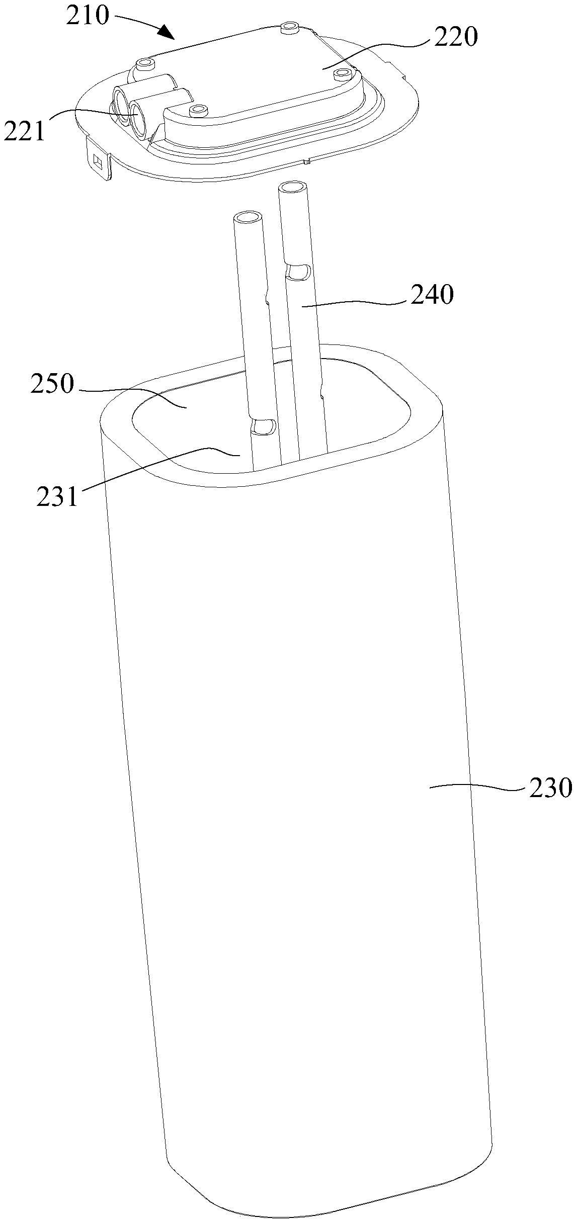
[0051] In an embodiment of the present invention, refer to Figure 1 to Figure 6 , The water bag 210 includes:
[0052] The bag body 230, the bag body 230 has an opening 231;
[0053] The base 220 is hermetically connected with the edge of the opening 231, the base 220 and the bag body 230 form a water storage cavity 250, and the base 220 is provided with a water channel connecting the water storage cavity 250 and the outside 221; and,
[0054] The air path 227 communicates with the top of the water storage cavity 250 and the water path 221.
[0055] Specifically, the water bag 210 is used as a water storage device in the water purifier 1, and can store pure water purified in the water purifier 1 in the water bag 210, which is convenient for users to use water. The water bag 210 mainly includes a bag body 230 and a base 220. The bag body 230 is usually made of flexible materials and has better flexibility. When water is poured into the water bag 210, the bag body 230 can expand; when the water bag 210 emits water When the time, the water bag 210 can be contracted; the bag body 230 has an opening 231, the edge of the opening 231 is connected to the base 220 in a sealed manner, the base 220 covers the opening 231, and the base 220 and the bag body 230 form a water storage Cavities 250. Wherein, a water passage 221 is formed on the base 220, and the water passage 221 respectively communicates with the outside and the water storage cavity 250, so that the water purification pipeline of the water purifier 1 can be easily communicated with the water storage cavity 250.
[0056] It is understandable that air often remains in the water storage cavity 250 of the water bag 210. When the water bag 210 is filled with water, the air needs to be discharged from the water bag 210 so that water can better flow into the water storage cavity 250. When the water bag 210 is filled with water, the water flows to the bottom of the bag body 230, so that air is concentrated toward the top of the water storage cavity 250. At this time, the air passage 227 is provided so that the air at the top of the water storage cavity 250 can pass through the air passage 227 flows out of the water bag 210 from the waterway channel 221, so that the air in the water bag 210 can be easily discharged, avoiding that the air in the water bag 210 cannot be discharged and the internal pressure of the water bag 210 is large, which will cause the water bag 210 to lose the water intake effect. Good defect. There are many ways to form the air passage 227. For example, a gas pipe can be provided to connect the water passage 221 and the top of the water storage cavity 250, etc., which are not specifically limited here.
[0057] In addition, there are many ways of sealing connection between the base 220 and the bag body 230, for example, the base 220 and the bag body 230 are sealed and connected by means of adhesive, hot melt welding or ultrasonic welding. It is worth noting that the base 220 and the bag body 230 may both be made of plastic materials. At this time, the base 220 and the bag body 230 may be sealed and connected by heat welding or ultrasonic welding. The sealing performance between the bag bodies 230 is better and the connection strength is better, so that the structure of the water bag 210 is also more stable. In some preferred embodiments, the base 220 and the bag body 230 are made of TPU (thermoplastic polyurethane elastomer rubber) material.
[0058] The technical solution of the present invention connects the top of the water storage cavity 250 with the water path 221 on the base 220 by setting the air path 227, and then realizes the effect that the top of the water storage cavity 250 is connected to the outside world. When the water bag 210 When water is injected, the air at the top of the water storage cavity 250 can be discharged to the outside through the air passage 227 and the water passage 221, so that the pressure in the water storage cavity 250 can be kept consistent with the outside pressure, which is more conducive to the water injection of the water bag 210 and prevents water The residual air in the bag 210 occupies the volume of the water storage cavity 250, which ensures the effective water injection volume of the water bag 210.
[0059] Further, the base 220 is located at the top of the bag body 230, and the opening 231 of the bag body 230 is also located at the top of the bag body 230. As a result, the top of the water storage cavity 250 is in contact with the base 220, thereby facilitating the air passage The channel 227 is provided on the base 220, thereby avoiding an additional air pipe in the bag body 230, so that the structure of the water bag 210 is more compact.
[0060] It is worth noting that in this embodiment, the above-mentioned water passage 221 preferably includes a water inlet passage 222 and a water outlet passage 223. The water inlet passage 222 and the water outlet passage 223 respectively communicate with the water storage cavity 250, and the air passage passage 227 communicates with the water outlet passage 223. And the water storage cavity 250. At this time, water enters the water storage cavity 250 from the water inlet channel 222, and the air in the water storage cavity 250 is discharged from the water bag 210 through the air channel 227 and the water outlet channel 223.
[0061] Further, refer to Figure 3 to Figure 7 The water bag 210 preferably further includes a water pipe 240, which is located in the water storage cavity 250. The water pipe 240 is U-shaped. One end of the water pipe 240 is connected to the water inlet channel 222, and the other end is connected to the water outlet channel 223. The water pipe 240 is provided with a first flow-through gap 244 at a position close to the bottom of the bag body 230. When the water bag 210 is filled with water, the water flow can flow through the water inlet channel 222 and the water guide tube 240 from the first flow gap 244 into the water storage cavity 250; when the water bag 210 is out of water, the water in the water storage cavity 250 can flow from the first The flow gap 244 flows out through the water guiding pipe 240 and the water outlet channel 223.
[0062] Further, in some preferred embodiments, the water guiding pipe 240 is also provided with a plurality of second flow-through gaps 245, and the multiple second flow-through gaps 245 are arranged at intervals along the extension direction of the water guiding pipe 240, so that the water It is easier to circulate between the water pipe 240 and the water storage cavity 250, and the water inlet and outlet effects of the water bag 210 are improved. Wherein, the orientation of at least two of the plurality of second flow-through gaps 245 is different, so that the water in the water storage cavity 250 and the water pipe 240 can circulate better.
[0063] It should be noted that, for the above-mentioned water guiding pipe 240, the water guiding pipe 240 includes a water inlet section 241, a curved section 242, and a water outlet section 243 connected in sequence. The water inlet section 241 is in communication with the water inlet channel 222, and the water outlet channel 223 is connected with the water outlet channel. 223 is connected, the curved section 242 is provided with a first flow-through gap 244, the outlet section 243 is provided with a plurality of second flow-through gaps 245, and the plurality of second flow-through gaps 245 are arranged at intervals along the extending direction of the water outlet section 243. At this time, the water outlet effect of the water bag 210 can be significantly improved. Of course, a plurality of second through-flow gaps 245 may also be provided on the water inlet section 241 to improve the water inlet effect of the water bag 210.
[0064] In addition, in a preferred embodiment of the present invention, refer to Figure 5 with Image 6 The above-mentioned air passage 227 is preferably a vent 228 opened on the base 220. At this time, the vent 228 communicates with the water storage chamber 250 and the water passage 221 (further preferably the water outlet passage 223). At this time, the structure of the air passage 227 It is relatively simple and easy to implement on the base 220, thereby simplifying the structure of the water bag 210 and making the structure of the water bag 210 more compact.
[0065] Further, for the base 220, the side of the base 220 facing the water storage cavity 250 is provided with a groove 229, the water passage 221 is located at the bottom of the groove 229, and the groove 229 is in communication with the water storage cavity 250 , Thereby increasing the effective water storage volume of the water storage cavity 250.
[0066] In this embodiment, the water passage 221 located on the base 220 includes an external water conducting section 224, a connecting section 225, and an internal water conducting section 226 that are connected in sequence. The external water conducting section 224 is in communication with the outside, and the internal water conducting section 226 is connected to the storage. The water cavity 250 is in communication; the external water guiding section 224 and the connecting section 225 extend in the plane where the bottom of the groove 229 is located, and the air passage 227 is opened on the external water guiding section 224 and/or the connecting section 225. The internal water guiding section 226 extends from the bottom of the groove 229 toward the water storage cavity 250. At this time, when the water channel 221 is formed on the base 220, the thickness of the base 220 itself will not be too large, which reduces the material used for the base 220 and saves costs; on the other hand, the base 220 faces a side of the water storage cavity 250. The side is not too protruding, and the outer water guiding section 224 is prevented from facing the side of the base 220 facing away from the water storage cavity 250, which can reduce the occupation of the internal space of the water purifier 1 by the water bag 210.
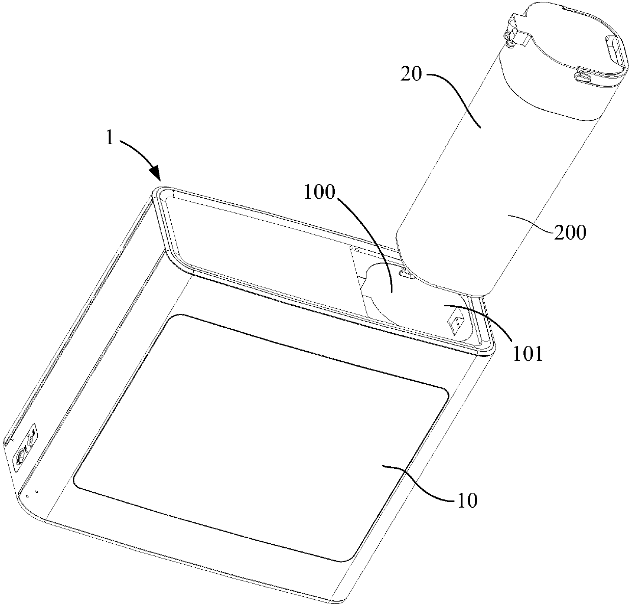
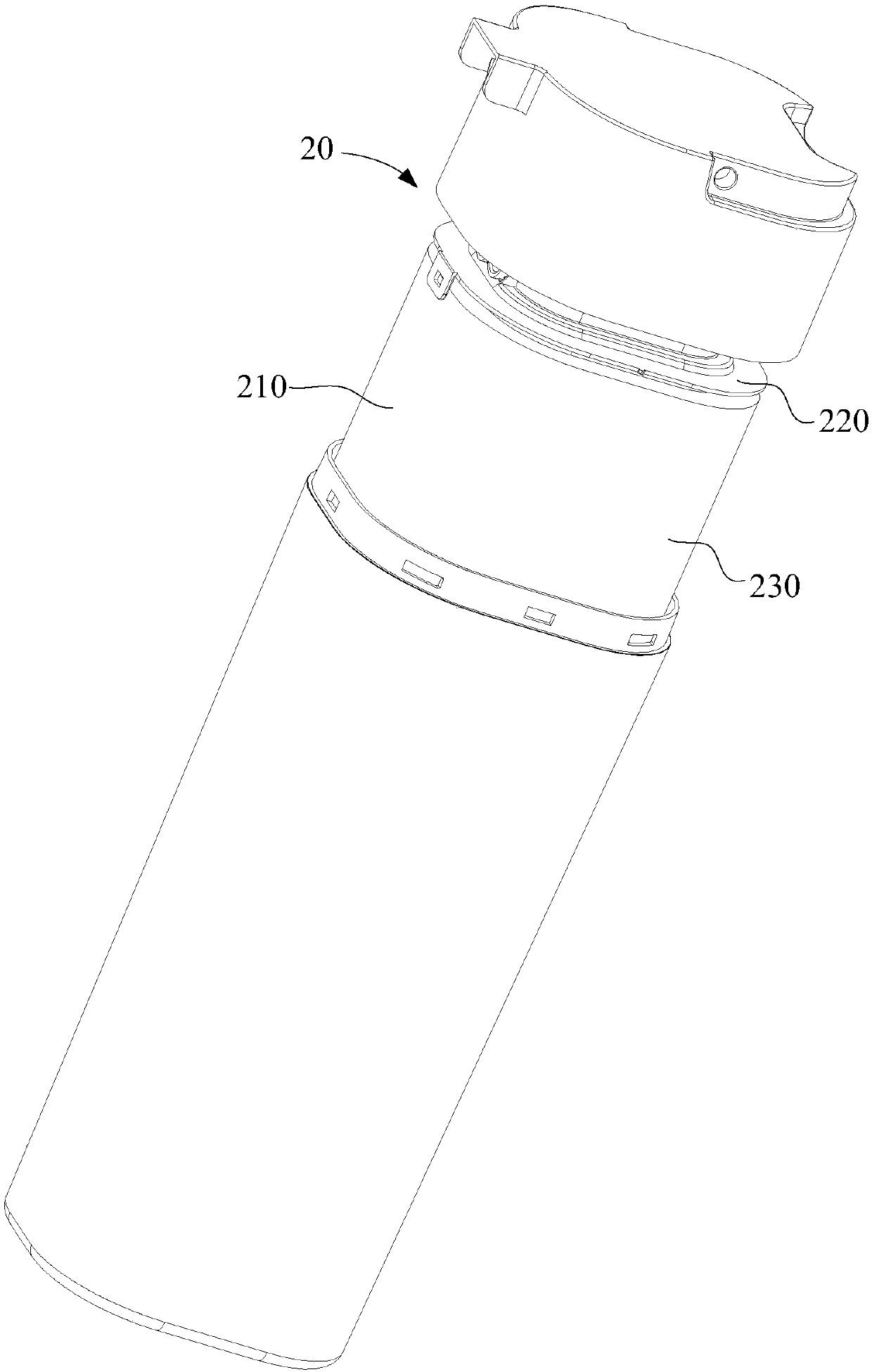
[0067] Reference figure 1 with figure 2 The present invention also provides a pressure tank 20. The pressure tank 20 includes a tank body 200 and a water bag 210. The water bag 210 is arranged in the tank body 200. The specific structure of the water bag 210 refers to the above-mentioned embodiment. 20 adopts all the technical solutions of all the foregoing embodiments, and therefore at least has all the beneficial effects brought about by the technical solutions of the foregoing embodiments, and will not be repeated here.
[0068] Reference figure 1 The present invention also provides a water purifier 1, which includes a housing 10 and a pressure tank 20. The housing 10 is formed with a receiving cavity 100 with an opening 101, and the pressure tank 20 is self-contained. The opening 101 can be accommodated in the receiving cavity 100 in a retractable manner. The specific structure of the pressure tank 20 refers to the above-mentioned embodiment. Since the water purifier 1 adopts all the technical solutions of all the above-mentioned embodiments, it has at least all the beneficial effects brought by the technical solutions of the above-mentioned embodiments, and will not be omitted here. Go into details one by one.
[0069] It is worth noting that the opening 101 of the accommodating cavity 100 may be located on the top of the housing 10 or on the side wall of the housing 10, which is not specifically limited here. Wherein, when the opening 101 is at the top of the housing 10, the pressure tank 20 is retractably accommodated in the accommodating cavity 100 in the up and down direction; when the opening 101 is at the top of the housing 10, the pressure tank 20 is horizontally It can be accommodated in the receiving cavity 100 in a retractable manner. Of course, in some other embodiments, the pressure tank 20 may also be arranged obliquely in the housing 10, at this time, there is a certain angle between the drawing direction of the pressure tank 20 and the horizontal plane.
PUM


Description & Claims & Application Information
We can also present the details of the Description, Claims and Application information to help users get a comprehensive understanding of the technical details of the patent, such as background art, summary of invention, brief description of drawings, description of embodiments, and other original content. On the other hand, users can also determine the specific scope of protection of the technology through the list of claims; as well as understand the changes in the life cycle of the technology with the presentation of the patent timeline. Login to view more.