Floating roller mechanism and bill processing device

A floating roller and frame technology, applied in thin material handling, transportation and packaging, object supply, etc., can solve problems such as affecting the movement of the tail of the bill and affecting the correction mechanism to correct the bill.

Active Publication Date: 2021-03-19
SHANDONG NEW BEIYANG INFORMATION TECH CO LTD
View PDF5 Cites 0 Cited by
  • Summary
  • Abstract
  • Description
  • Claims
  • Application Information

AI Technical Summary

Problems solved by technology

[0003] The existing financial bill processing device is equipped with a scanning mechanism for scanning the information on the surface of the bill, a correction mechanism for correcting the bill, and a printing mechanism for printing on the bill surface. There are conveying roller sets, each conveying roller set includes a conveying roller and a floating roller elastically pressed on the driving roller, a bill conveying channel is formed between the conveying roller and the floating roller, and the two conveying roller sets convey After the bill passes through the scanning mechanism, the scanned bill enters the correction mechanism for deviation correction, so as to prevent the deviation of the printing position and the incomplete face of the archived bill when the skewed bill moves to the printing mechanism. At this time, the tail of the bill is pressed between the floating roller and the conveying roller, which affects the movement of the tail of the bill, thereby affecting the correcting mechanism to correct the bill

Method used


Image

  • Floating roller mechanism and bill processing device
  • Floating roller mechanism and bill processing device
  • Floating roller mechanism and bill processing device

Examples


Embodiment Construction

[0029] The technical solutions of the present invention will be clearly and completely described below in conjunction with the accompanying drawings. Apparently, the described embodiments are some of the embodiments of the present invention, but not all of them. Based on the embodiments of the present invention, all other embodiments obtained by persons of ordinary skill in the art without making creative efforts belong to the protection scope of the present invention.

[0030] In the description of the present invention, it should be noted that the terms "center", "upper", "lower", "left", "right", "vertical", "horizontal", "inner", "outer" etc. The indicated orientation or positional relationship is based on the orientation or positional relationship shown in the drawings, and is only for the convenience of describing the present invention and simplifying the description, rather than indicating or implying that the referred device or element must have a specific orientation, ...


PUM


Abstract

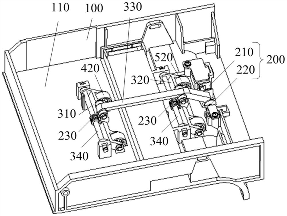
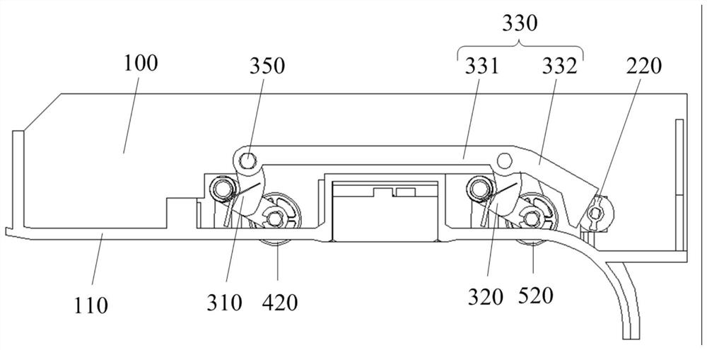
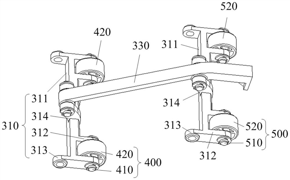
The invention provides a floating roller mechanism and a bill processing device and relates to the technical field of financial machinery. The floating roller mechanism comprises a machine frame, a drive assembly, a supporting assembly, a first floating roller and a second floating roller. The first floating roller and the second floating roller are supported by the supporting assembly, the firstfloating roller and the second floating roller are arranged in parallel in a spaced manner and both can freely rotate around own axes. The supporting assembly is movably connected with the machine frame. The drive assembly is in transmission connection with the supporting assembly. The drive assembly is configured to drive the supporting assembly to be located at a first position or a second position relative to the machine frame. When the supporting assembly is located at the first position, the first floating roller and the second floating roller conduct downward press at the same time. Whenthe supporting assembly is located at the second position, the first floating roller and the second floating roller rise at the same time. The floating roller mechanism relieves the technical problemthat in a relevant technology, since the position of the floating roller is fixed, bill deviation correcting by a deviation correcting mechanism is influenced.

Description

technical field [0001] The invention relates to the technical field of financial machinery, in particular to a floating roller mechanism and a financial bill processing device. Background technique [0002] Financial bills are bills issued by financial institutions or financial institutions undertake payment obligations. my country's existing financial instruments include bills of exchange, checks and promissory notes. Financial institutions use a financial bill processing device to issue financial bills. The financial bill processing device usually includes a ticket box and a printing mechanism. The ballot box is used to store financial bills, and the printing mechanism is used to print information such as account name, account number and amount on the surface of the financial bill. [0003] The existing financial bill processing device is equipped with a scanning mechanism for scanning the information on the surface of the bill, a correction mechanism for correcting the b...

Claims


Application Information

Patent Timeline
Patent Type & Authority Patents(China)
IPC IPC(8): B65H5/06
CPCB65H5/062B65H2404/142B65H2404/152B65H2701/1912B65H2801/06B65H2801/39
Inventor 高明董晓博段续丛强滋
Owner SHANDONG NEW BEIYANG INFORMATION TECH CO LTD
Why Eureka
Try Eureka